
ESP32 and DRV8833-Based Battery-Powered Motor Control System with MPU6050 Integration
View and Edit Project In Cirkit Designer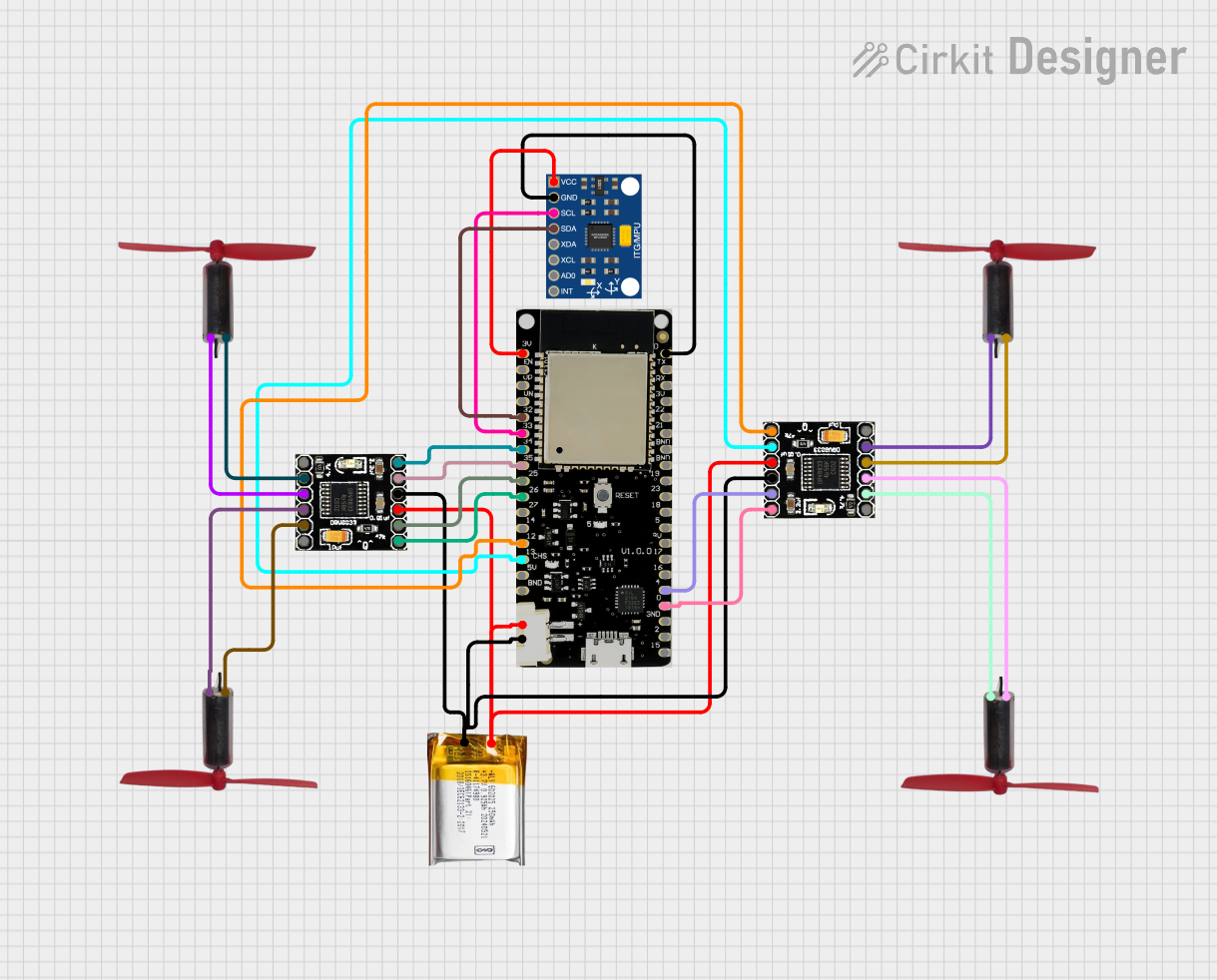
Circuit Documentation
Summary
This document provides a detailed overview of a circuit that includes motor drivers, a microcontroller, a battery, and an inertial measurement unit (IMU). The circuit is designed to control multiple coreless motors using an ESP32 microcontroller, with power supplied by a 3.7V LiPo battery. The IMU is used for motion sensing.
Component List
Drv8833 Motor Driver
- Description: Dual H-Bridge motor driver
- Pins: EEP, OUT1, OUT2, OUT3, OUT4, ULT, IN4, IN3, GND, VCC, IN1, IN2
3.7V LiPo Battery
- Description: Lithium Polymer battery
- Pins: +Ve, GND
ESP32 Lolin32
- Description: Microcontroller with Wi-Fi and Bluetooth capabilities
- Pins: 3.3V, EN, VP, VN, 32, 33, 34, 35, 25, 26, 27, 14, 12, 13, 5V, GND, TX, RX, 22, 21, 15, 2, 0, 4, 16, 17, 5, 18, 23, 19, B+, B-
InvenSense MPU6050
- Description: 6-axis IMU (3-axis gyroscope + 3-axis accelerometer)
- Pins: VCC, GND, SCL, SDA, XDA, XCL, AD0, INT
Coreless Motor Clock
- Description: Coreless motor
- Pins: +, -
Wiring Details
Drv8833 Motor Driver 1
- OUT1 connected to Coreless Motor Clock pin -
- OUT2 connected to Coreless Motor Clock pin +
- OUT3 connected to Coreless Motor Clock pin -
- OUT4 connected to Coreless Motor Clock pin +
- IN4 connected to ESP32 Lolin32 pin 34
- IN3 connected to ESP32 Lolin32 pin 35
- GND connected to Drv8833 Motor Driver 2 pin GND, ESP32 Lolin32 pin B-, and 3.7V LiPo Battery pin GND
- VCC connected to Drv8833 Motor Driver 2 pin VCC, ESP32 Lolin32 pin B+, and 3.7V LiPo Battery pin +Ve
- IN1 connected to ESP32 Lolin32 pin 25
- IN2 connected to ESP32 Lolin32 pin 26
Drv8833 Motor Driver 2
- OUT1 connected to Coreless Motor Clock pin -
- OUT2 connected to Coreless Motor Clock pin +
- OUT3 connected to Coreless Motor Clock pin -
- OUT4 connected to Coreless Motor Clock pin +
- IN4 connected to ESP32 Lolin32 pin 0
- IN3 connected to ESP32 Lolin32 pin 4
- IN1 connected to ESP32 Lolin32 pin 13
- IN2 connected to ESP32 Lolin32 pin 12
3.7V LiPo Battery
- +Ve connected to Drv8833 Motor Driver 1 pin VCC, Drv8833 Motor Driver 2 pin VCC, and ESP32 Lolin32 pin B+
- GND connected to Drv8833 Motor Driver 1 pin GND, Drv8833 Motor Driver 2 pin GND, and ESP32 Lolin32 pin B-
ESP32 Lolin32
- 34 connected to Drv8833 Motor Driver 1 pin IN4
- 35 connected to Drv8833 Motor Driver 1 pin IN3
- 25 connected to Drv8833 Motor Driver 1 pin IN1
- 26 connected to Drv8833 Motor Driver 1 pin IN2
- 0 connected to Drv8833 Motor Driver 2 pin IN4
- 4 connected to Drv8833 Motor Driver 2 pin IN3
- 13 connected to Drv8833 Motor Driver 2 pin IN1
- 12 connected to Drv8833 Motor Driver 2 pin IN2
- 3.3V connected to InvenSense MPU6050 pin VCC
- 32 connected to InvenSense MPU6050 pin SDA
- 33 connected to InvenSense MPU6050 pin SCL
- GND connected to InvenSense MPU6050 pin GND
InvenSense MPU6050
- VCC connected to ESP32 Lolin32 pin 3.3V
- SDA connected to ESP32 Lolin32 pin 32
- SCL connected to ESP32 Lolin32 pin 33
- GND connected to ESP32 Lolin32 pin GND
Coreless Motor Clock 1
- + connected to Drv8833 Motor Driver 1 pin OUT2
- - connected to Drv8833 Motor Driver 1 pin OUT1
Coreless Motor Clock 2
- + connected to Drv8833 Motor Driver 1 pin OUT4
- - connected to Drv8833 Motor Driver 1 pin OUT3
Coreless Motor Clock 3
- + connected to Drv8833 Motor Driver 2 pin OUT2
- - connected to Drv8833 Motor Driver 2 pin OUT1
Coreless Motor Clock 4
- + connected to Drv8833 Motor Driver 2 pin OUT4
- - connected to Drv8833 Motor Driver 2 pin OUT3
Documented Code
ESP32 Lolin32 Code
void setup() {
  // put your setup code here, to run once:

}

void loop() {
  // put your main code here, to run repeatedly:

}
This code is a basic template for the ESP32 microcontroller. The setup function is called once when the microcontroller starts, and the loop function runs continuously. You can add your motor control and IMU reading logic in these functions.