
Circuit Documentation
Summary
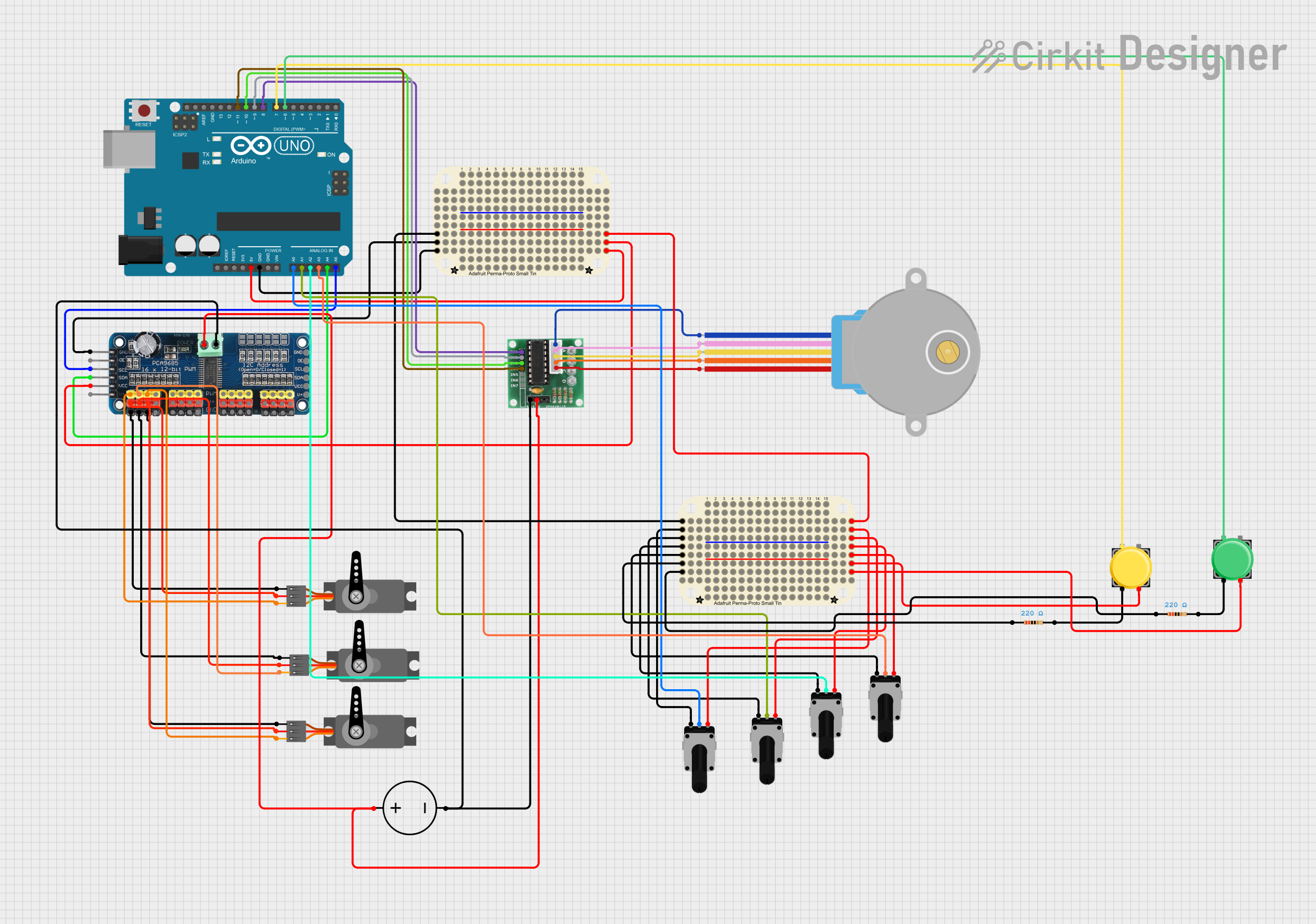
This document provides a detailed overview of a circuit designed to interface an Arduino UNO with various peripherals including a ULN 2003 driver for a stepper motor, a 16-Channel PWM Servo Driver for multiple servos, rotary potentiometers for analog input, and pushbuttons with pull-up resistors. The circuit is powered by a DC power source and utilizes two Adafruit Perma Proto Small Mint boards for prototyping and connections.
Component List
Arduino UNO
- Microcontroller board based on the ATmega328P
- Provides digital I/O pins, analog inputs, and various power outputs
ULN 2003
- 7-channel Darlington array used for driving high-current loads
- Interfaces with the Arduino to control a stepper motor
16-Channel PWM Servo Driver
- I2C-based PWM driver capable of controlling 16 servos
- Receives commands from the Arduino via I2C communication
Servo (x3)
- Rotary actuators with position control via PWM signals
- Powered and controlled by the 16-Channel PWM Servo Driver
28BYJ-48 Stepper Motor
- Small, 5-wire unipolar stepper motor
- Driven by the ULN 2003 connected to the Arduino
DC Power Source
- Provides power to the circuit
- Ground and positive terminals are distributed to various components
Rotary Potentiometer (x4)
- Variable resistors with a 10k Ohm resistance
- Provide analog input to the Arduino for control purposes
Adafruit Perma Proto Small Mint (x2)
- Prototyping boards used for making semi-permanent circuit connections
- Facilitate the organization and wiring of components
Pushbutton (x2)
- Momentary tactile switches
- Used for triggering events or actions in the circuit
Resistor (x2)
- 220 Ohm resistors
- Serve as pull-up resistors for the pushbuttons
Wiring Details
Arduino UNO
- 5V and GND pins provide power to the circuit
- Analog inputs A0-A3 are connected to the wipers of the rotary potentiometers
- Digital pins D6-D11 interface with the pushbuttons and the ULN 2003
- I2C pins A4 (SDA) and A5 (SCL) are connected to the 16-Channel PWM Servo Driver
ULN 2003
- Input pins IN1-IN4 are controlled by Arduino digital pins D8-D11
- Output pins COIL1-COIL5 are connected to the corresponding pins of the stepper motor
- GND and + are connected to the ground and positive terminals of the DC power source
16-Channel PWM Servo Driver
- SDA and SCL are connected to Arduino pins A4 and A5 for I2C communication
- VCC and GND are connected to the 5V and GND rails on the prototyping board
- PWM outputs PWM1-PWM3 are connected to the PWM inputs of the servos
- V+ and Vin- are connected to the positive and ground terminals of the DC power source
Servos
- PWM inputs are connected to the corresponding PWM outputs on the PWM Servo Driver
- VCC and GND are connected to the V+ and GND outputs on the PWM Servo Driver
Rotary Potentiometers
- Wipers are connected to the Arduino analog inputs A0-A3
- One leg is connected to the 5V rail, and the other leg is connected to the ground rail
Pushbuttons
- One pin is connected to the Arduino digital pins D6 and D7
- The opposite pin is connected to the 5V rail through a 220 Ohm resistor
Resistor
- Connected between the pushbutton and the 5V rail
- Provides a pull-up for the pushbutton to ensure a stable high signal when not pressed
Documented Code
Arduino UNO Code (sketch.ino)
void setup() {
  // put your setup code here, to run once:

}

void loop() {
  // put your main code here, to run repeatedly:

}
This code is a template for the Arduino UNO and does not contain any specific functionality. It provides the basic structure for an Arduino sketch with setup() and loop() functions. The setup() function is intended for initialization code that runs once, while the loop() function contains code that runs repeatedly.
Additional Notes
- The provided code does not include any specific logic or functionality.
- The actual implementation should include code to read the analog inputs from the potentiometers, control the stepper motor via the ULN 2003, and handle the PWM signals for the servos.
- The pushbuttons should be debounced either in hardware or software to ensure reliable operation.
- The I2C communication with the PWM Servo Driver should be established and tested to control the servos.