
Arduino 101-Based Real-Time Clock and Display with Buzzer Alert
View and Edit Project In Cirkit Designer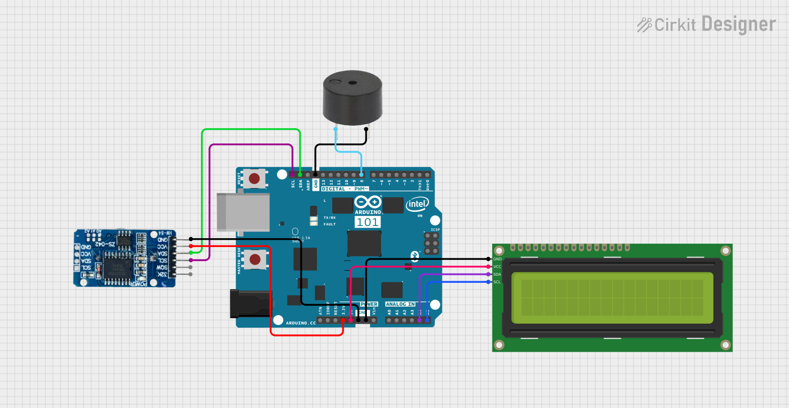
Circuit Documentation
Summary
This circuit involves an Arduino 101 microcontroller interfacing with an RTC DS3231 real-time clock module, a 16x2 I2C LCD display, and a buzzer. The Arduino 101 serves as the central controller, managing timekeeping, display, and sound functionalities.
Component List
RTC DS3231
- Description: Real-time clock module
- Pins: 32K, SQW, SCL, SDA, VCC, GND
- Purpose: Provides accurate timekeeping
Arduino 101
- Description: Microcontroller board
- Pins: A5/SCL, A4/SDA, AREF, GND, D13/SCK, D12/MISO, D11 PWM/MOSI, D10 PWM/SS, D9 PWM, D8, D7, D6 PWM, D5 PWM, D4, D3 PWM, D2, D1/TX, D0/RX, AIN, ioref, RESET, 3V3, 5V, VIN, A0, A1, A2, A3, ICSP MISO, ICSP SCK, ICSP MOSI
- Purpose: Central controller for the circuit
16x2 I2C LCD
- Description: 16x2 character LCD display with I2C interface
- Pins: GND, VCC, SDA, SCL
- Purpose: Displays information
Buzzer
- Description: Sound-producing device
- Pins: PIN, GND
- Purpose: Produces sound alerts
Wiring Details
RTC DS3231
- SCL connected to Arduino 101 A5/SCL
- SDA connected to Arduino 101 A4/SDA
- VCC connected to Arduino 101 3V3
- GND connected to Arduino 101 GND
Arduino 101
- A5/SCL connected to RTC DS3231 SCL and 16x2 I2C LCD SCL
- A4/SDA connected to RTC DS3231 SDA and 16x2 I2C LCD SDA
- 3V3 connected to RTC DS3231 VCC
- 5V connected to 16x2 I2C LCD VCC
- GND connected to RTC DS3231 GND, 16x2 I2C LCD GND, and Buzzer GND
- D8 connected to Buzzer PIN
16x2 I2C LCD
- SCL connected to Arduino 101 A5/SCL
- SDA connected to Arduino 101 A4/SDA
- VCC connected to Arduino 101 5V
- GND connected to Arduino 101 GND
Buzzer
- PIN connected to Arduino 101 D8
- GND connected to Arduino 101 GND
Code
No code provided for this circuit.