
Circuit Documentation
Summary
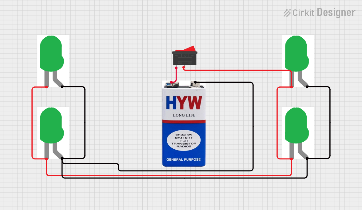
This circuit consists of four green LEDs, a 9V battery, and a rocker switch. The LEDs are connected in parallel, and their cathodes are connected to the rocker switch. The anodes of the LEDs are connected to the negative terminal of the 9V battery. The positive terminal of the battery is connected to the rocker switch. When the switch is turned on, the circuit is completed, and the LEDs light up.
Component List
LED: Two Pin (green)
- Description: A green LED with two pins: cathode and anode.
- Purpose: To emit green light when current flows through it.
9V battery
- Description: A 9V battery with two terminals: positive (+) and negative (-).
- Purpose: To provide power to the circuit.
Rocker Switch
- Description: A switch with two pins: 1 and 2.
- Purpose: To control the flow of current in the circuit.
Wiring Details
LED: Two Pin (green)
Cathode:
- Connected to the cathodes of the other three LEDs.
- Connected to pin 2 of the rocker switch.
Anode:
- Connected to the anodes of the other three LEDs.
- Connected to the negative terminal of the 9V battery.
9V battery
Positive (+):
- Connected to pin 1 of the rocker switch.
Negative (-):
- Connected to the anodes of the four LEDs.
Rocker Switch
Pin 1:
- Connected to the positive terminal of the 9V battery.
Pin 2:
- Connected to the cathodes of the four LEDs.
Documented Code
There is no microcontroller code associated with this circuit.