Arduino UNO Controlled Robot with Ultrasonic Sensor and Dual Motor Drivers
Circuit Documentation
Summary of the Circuit
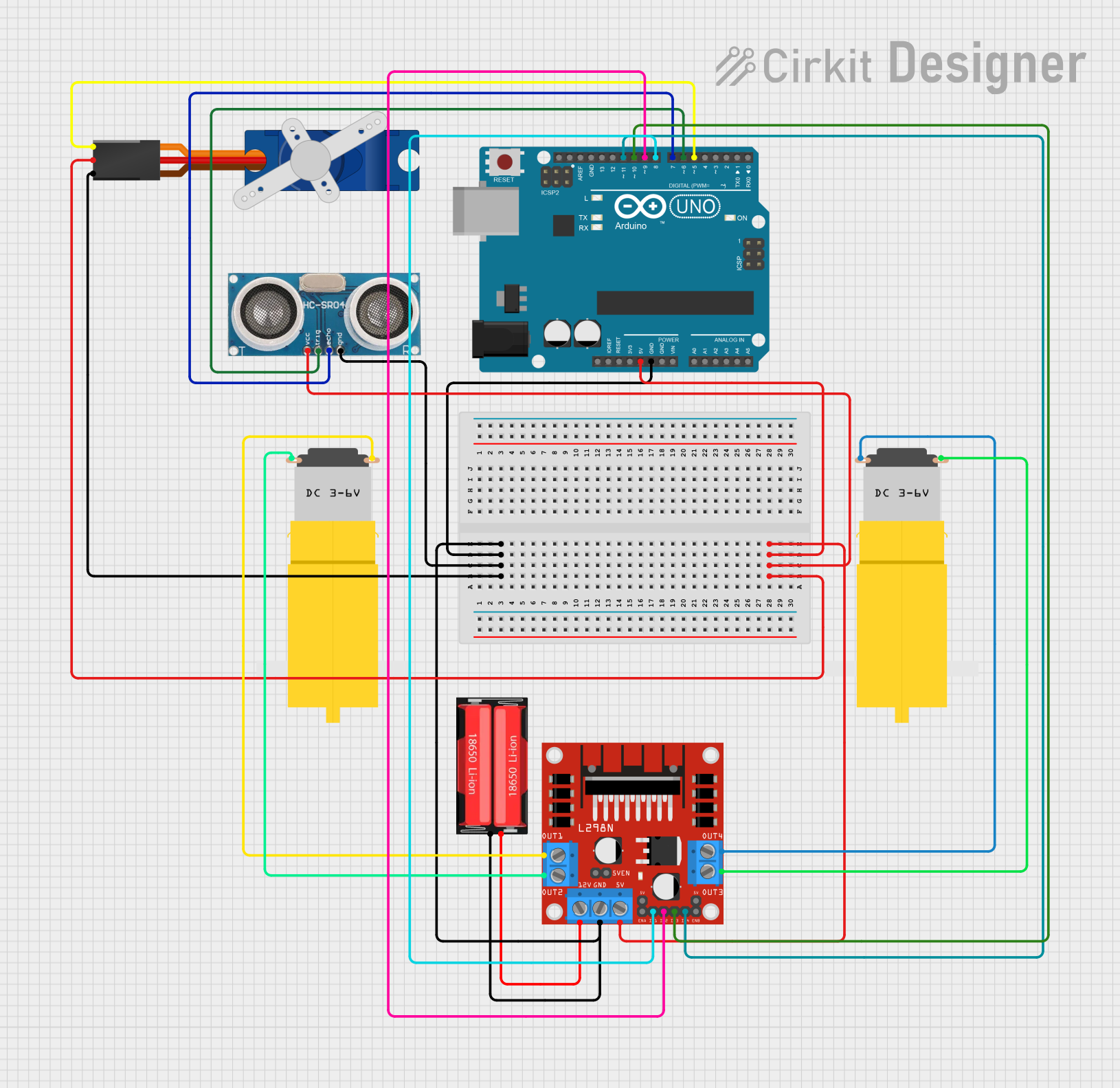
This circuit is designed to control a pair of DC motors using an L298N motor driver module, interfaced with an Arduino UNO microcontroller. It also includes a Tower Pro SG90 servo motor and an ultrasonic sensor for additional functionalities such as distance measurement or object detection. The power supply for the circuit is provided by a 18650 Li-Ion battery. The Arduino UNO is responsible for controlling the behavior of the motors and the servo, as well as processing the signals from the ultrasonic sensor.
Component List
Arduino UNO
- Microcontroller board based on the ATmega328P
- It has 14 digital input/output pins, 6 analog inputs, a 16 MHz quartz crystal, a USB connection, a power jack, an ICSP header, and a reset button.
18650 Li-Ion Battery
- Rechargeable lithium-ion battery
- Provides power to the circuit.
L298N DC Motor Driver
- A dual H-bridge motor driver module
- Capable of driving two DC motors or one stepper motor.
Tower Pro SG90 Servo
- A small and lightweight servo motor
- Capable of precise position control.
Ultrasonic Sensor
- Used for measuring distance to an object using ultrasonic waves.
Motor Amarillo Motorreductor Hobby (x2)
- A yellow hobby gear motor
- Used for applications requiring simple DC motors with gear reduction.
Wiring Details
Arduino UNO
5Vpin connected to the 5V power busGNDpin connected to the ground bus- Digital pins
D5toD11are used to interface with the servo, ultrasonic sensor, and motor driver.
18650 Li-Ion Battery
Positiveterminal connected to the12Vinput of the L298N motor driverNegativeterminal connected to the ground bus
L298N DC Motor Driver
5Vpin connected to the 5V power busGNDpin connected to the ground bus12Vpin connected to the positive terminal of the 18650 Li-Ion batteryIN1toIN4pins connected to Arduino UNO digital pinsD8toD11OUT1toOUT4pins connected to the terminals of the two DC motors
Tower Pro SG90 Servo
Signalpin connected to Arduino UNO digital pinD5+5Vpin connected to the 5V power busGNDpin connected to the ground bus
Ultrasonic Sensor
+VCCpin connected to the 5V power busGNDpin connected to the ground busTriggerpin connected to Arduino UNO digital pinD6Echopin connected to Arduino UNO digital pinD7
Motor Amarillo Motorreductor Hobby
- One motor's
vccandGNDpins connected toOUT1andOUT2of the L298N motor driver - The other motor's
vccandGNDpins connected toOUT3andOUT4of the L298N motor driver
Documented Code
void setup() {
  // put your setup code here, to run once:

}

void loop() {
  // put your main code here, to run repeatedly:

}
The provided code is a template with the standard setup and loop functions for an Arduino sketch. The setup function is intended to contain initialization code that runs once when the microcontroller is powered on or reset. The loop function contains the main logic of the sketch, which runs repeatedly as long as the microcontroller is powered.
Additional code should be added to initialize the pins connected to the L298N motor driver, the servo, and the ultrasonic sensor. The logic to control the motors, read sensor data, and actuate the servo should also be implemented within the loop function.