Wi-Fi Controlled Smart Light with NodeMCU and Relay
Circuit Documentation
Summary
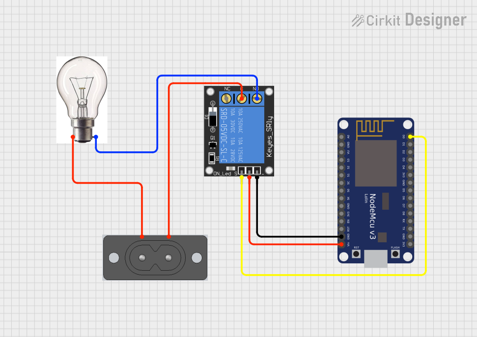
The circuit described in the provided inputs is a simple control system that uses a NodeMCU V3 ESP8266 microcontroller to operate a 1-Channel Relay, which in turn controls the power to a bulb. The relay is an electromechanical switch that allows the low-power NodeMCU to control the high-power circuit of the bulb. The bulb is connected to an AC power source through a 2 Prong AC Socket. The NodeMCU is powered by the same voltage source that powers the relay.
Component List
NodeMCU V3 ESP8266
- Description: A microcontroller board based on the ESP8266 chip, featuring WiFi capability.
- Pins: A0, GND, VU, S3, S2, S1, SC, S0, SK, 3V3, EN, RST, Vin, D0, D1, D2, D3, D4, D5, D6, D7, D8, RX, TX
1-Channel Relay (5V 10A)
- Description: An electromechanical switch that allows a low-power signal to control a higher power circuit.
- Pins: NC, signal, C, power, NO, ground
Bulb
- Description: An electric light source.
- Pins: +VE, -VE
2 Prong AC Socket
- Description: A connector for supplying AC power to the bulb.
- Pins: AC +, AC -
Wiring Details
NodeMCU V3 ESP8266
- GND connected to Relay ground
- Vin connected to Relay power
- D0 connected to Relay signal
1-Channel Relay (5V 10A)
- ground connected to NodeMCU GND
- power connected to NodeMCU Vin
- signal connected to NodeMCU D0
- C connected to 2 Prong AC Socket AC -
- NO connected to Bulb -VE
Bulb
- +VE connected to 2 Prong AC Socket AC +
- -VE connected to Relay NO
2 Prong AC Socket
- AC + connected to Bulb +VE
- AC - connected to Relay C
Documented Code
No code was provided for the microcontroller. Typically, the code would be responsible for controlling the relay by setting the D0 pin to a high or low state, which would open or close the relay and turn the bulb on or off. Since no code is available, it is assumed that the user will develop or provide the necessary code to control the relay via the NodeMCU V3 ESP8266.