
Arduino UNO-Based Automated Water Level Controller with 4X4 Keypad and I2C LCD
View and Edit Project In Cirkit Designer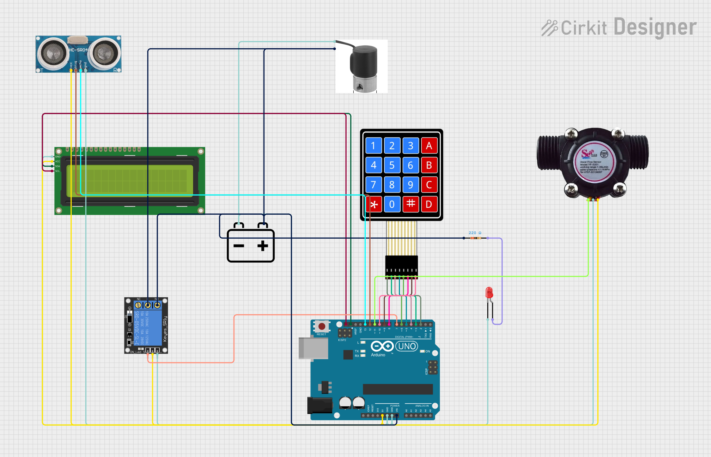
Circuit Documentation
Summary
This circuit is designed to control a water level monitoring and filling system using an Arduino UNO. The system includes a 4x4 membrane matrix keypad for user input, an ultrasonic sensor for measuring water level, a water flow sensor, a solenoid valve for controlling water flow, an LCD display for user interface, and an LED indicator. The Arduino UNO serves as the central microcontroller, coordinating all components.
Component List
4X4 Membrane Matrix Keypad
- Description: A keypad with 4 rows and 4 columns used for user input.
- Pins: R1, R2, R3, R4, C1, C2, C3, C4
Arduino UNO
- Description: A microcontroller board based on the ATmega328P.
- Pins: UNUSED, IOREF, Reset, 3.3V, 5V, GND, Vin, A0, A1, A2, A3, A4, A5, SCL, SDA, AREF, D13, D12, D11, D10, D9, D8, D7, D6, D5, D4, D3, D2, D1, D0
1-Channel Relay (5V 10A)
- Description: A relay module used to control high voltage devices.
- Pins: NC, signal, C, power, NO, ground
Water Flow Sensor
- Description: A sensor used to measure the flow rate of water.
- Pins: Signal, Vcc, GND
12V Battery
- Description: A power source providing 12V.
- Pins: -, +
16x2 I2C LCD
- Description: An LCD display with I2C interface for displaying information.
- Pins: GND, VCC, SDA, SCL
Solenoid Valve 12V
- Description: A valve controlled by a 12V signal to regulate water flow.
- Pins: GND, 12V
LED: Two Pin (red)
- Description: A red LED used as an indicator.
- Pins: cathode, anode
Resistor
- Description: A 220 Ohms resistor used to limit current.
- Pins: pin1, pin2
- Properties: Resistance: 220 Ohms
Ultrasonic Sensor
- Description: A sensor used to measure distance using ultrasonic waves.
- Pins: +VCC, Trigger, Echo, GND
Wiring Details
4X4 Membrane Matrix Keypad
- R1 to Arduino UNO D2
- R2 to Arduino UNO D3
- R3 to Arduino UNO D4
- R4 to Arduino UNO D5
- C1 to Arduino UNO D6
- C2 to Arduino UNO D8
- C3 to Arduino UNO D9
- C4 to Arduino UNO D10
Arduino UNO
- 5V to 1-Channel Relay (5V 10A) power, Water Flow Sensor Vcc, Ultrasonic Sensor +VCC, 16x2 I2C LCD VCC
- GND to 1-Channel Relay (5V 10A) ground, Solenoid Valve 12V GND, LED: Two Pin (red) cathode, Water Flow Sensor GND, Ultrasonic Sensor GND, 12V Battery -, 16x2 I2C LCD GND
- Vin to 12V Battery +
- SCL to 16x2 I2C LCD SCL
- SDA to 16x2 I2C LCD SDA
- D13 to Ultrasonic Sensor Echo
- D12 to Ultrasonic Sensor Trigger
- D11 to Water Flow Sensor Signal
- D7 to 1-Channel Relay (5V 10A) signal
1-Channel Relay (5V 10A)
- C to Resistor pin1
- NO to Resistor pin1
- Resistor pin2 to LED: Two Pin (red) anode
Water Flow Sensor
- Signal to Arduino UNO D11
12V Battery
- - to Arduino UNO GND
- + to Arduino UNO Vin
16x2 I2C LCD
- GND to Arduino UNO GND
- VCC to Arduino UNO 5V
- SDA to Arduino UNO SDA
- SCL to Arduino UNO SCL
Solenoid Valve 12V
- GND to Arduino UNO GND
- 12V to 1-Channel Relay (5V 10A) NO
LED: Two Pin (red)
- cathode to Arduino UNO GND
- anode to Resistor pin2
Resistor
- pin1 to 1-Channel Relay (5V 10A) C
- pin2 to LED: Two Pin (red) anode
Ultrasonic Sensor
- +VCC to Arduino UNO 5V
- Trigger to Arduino UNO D12
- Echo to Arduino UNO D13
- GND to Arduino UNO GND
Documented Code
#include <Wire.h>
#include <LiquidCrystal_I2C.h>
#include <Keypad.h>

// Define the LCD
LiquidCrystal_I2C lcd(0x27, 16, 2);

// Define the Keypad
const byte ROWS = 4; // Four rows
const byte COLS = 4; // Four columns
char keys[ROWS][COLS] = {
  {'1', '2', '3', 'A'},
  {'4', '5', '6', 'B'},
  {'7', '8', '9', 'C'},
  {'*', '0', '#', 'D'}
};
byte rowPins[ROWS] = {2, 3, 4, 5}; // Connect to the row pinouts of the keypad
byte colPins[COLS] = {6, 8, 9, 10}; // Connect to the column pinouts of the keypad
Keypad keypad = Keypad(makeKeymap(keys), rowPins, colPins, ROWS, COLS);

// Define the Ultrasonic Sensor
const int trigPin = 12;
const int echoPin = 13;

// Define the Flow Sensor
const int flowSensorPin = 11;

// Define the Solenoid Valve
const int solenoidValvePin = 7;

// Define the LED
const int ledPin = 6;

// Variables
float desiredWaterLevel = 0;
float currentWaterLevel = 0;
volatile int flowPulseCount = 0;
float flowRate = 0;
unsigned long oldTime = 0;

void setup() {
  // Initialize the LCD
  lcd.begin(16, 2); // Provide the number of columns and rows
  lcd.backlight();

  // Initialize the Serial Monitor
  Serial.begin(9600);

  // Initialize the Ultrasonic Sensor
  pinMode(trigPin, OUTPUT);
  pinMode(echoPin, INPUT);

  // Initialize the Flow Sensor
  pinMode(flowSensorPin, INPUT);
  attachInterrupt(digitalPinToInterrupt(flowSensorPin), flowPulseCounter, RISING);

  // Initialize the Solenoid Valve
  pinMode(solenoidValvePin, OUTPUT);
  digitalWrite(solenoidValvePin, LOW);

  // Initialize the LED
  pinMode(ledPin, OUTPUT);
  digitalWrite(ledPin, LOW);

  // Display initial message
  lcd.setCursor(0, 0);
  lcd.print("Enter Water Level:");
  Serial.println("Enter desired water level in cm:");
}

void loop() {
  // Read the desired water level from the Serial Monitor
  if (Serial.available() > 0) {
    String input = Serial.readStringUntil('\n');
    desiredWaterLevel = input.toFloat();
    lcd.setCursor(0, 1);
    lcd.print("Desired Level:");
    lcd.print(desiredWaterLevel);
    lcd.print(" cm");
    Serial.print("Desired Water Level Set: ");
    Serial.println(desiredWaterLevel);
    delay(2000);
    lcd.clear();
    lcd.setCursor(0, 0);
    lcd.print("Filling...");
    fillWater();
  }

  // Measure the current water level using the ultrasonic sensor
  currentWaterLevel = measureWaterLevel();

  // Display the current water level on the LCD
  lcd.setCursor(0, 1);
  lcd.print("Current Level:");
  lcd.print(currentWaterLevel);
  lcd.print(" cm");
  Serial.print("Current Water Level: ");
  Serial.println(currentWaterLevel);

  // Check if the desired water level is reached
  if (currentWaterLevel >= desiredWaterLevel) {