
Solar-Powered 3.7V Battery Charging System with BMS and Power Regulation
View and Edit Project In Cirkit Designer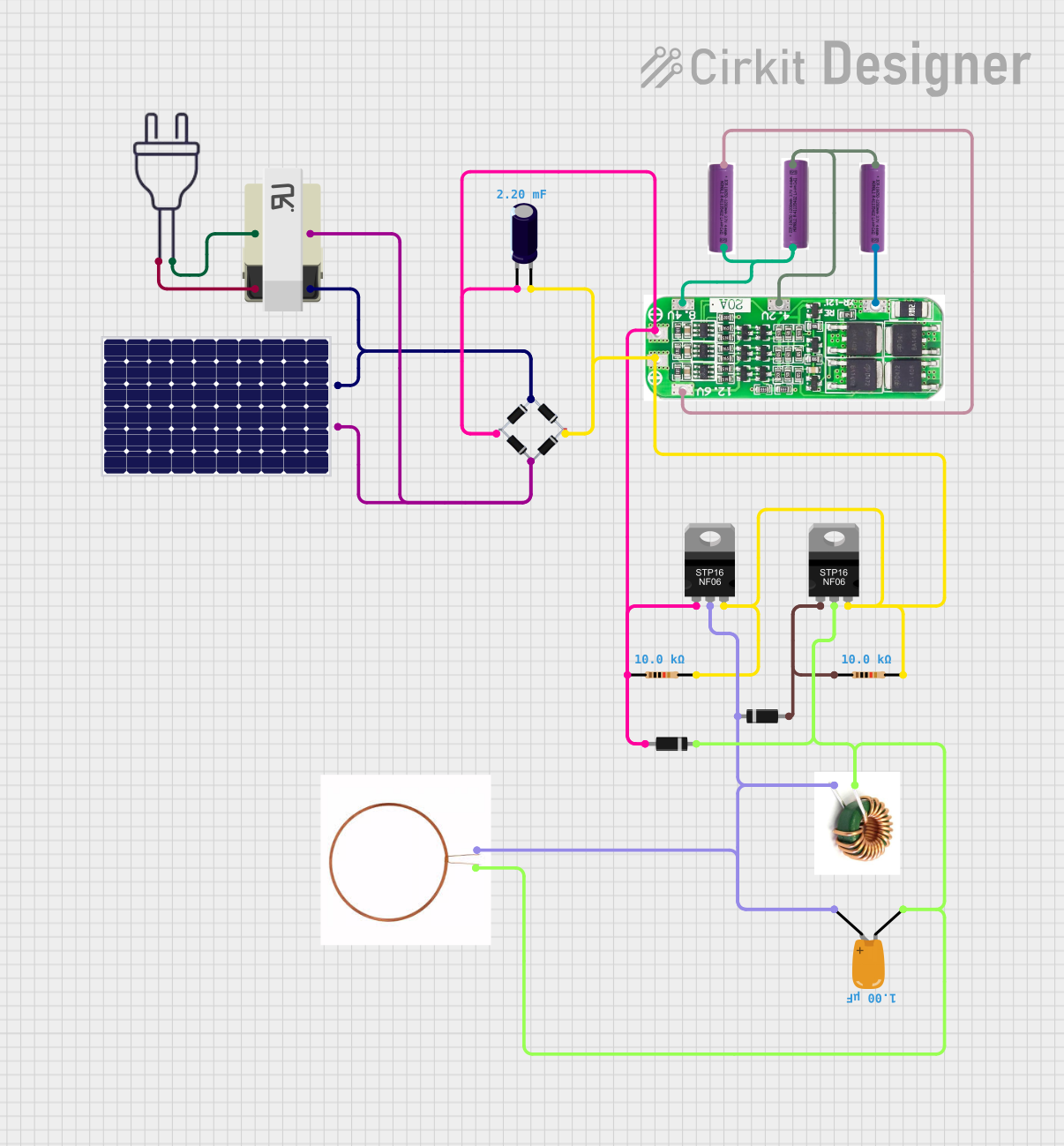
Circuit Documentation
Summary of the Circuit
This circuit appears to be a power supply system that utilizes a solar panel to charge a series of 3.7V batteries through a 3s 20A Battery Management System (BMS). The solar panel's output is rectified using a bridge rectifier and stabilized with capacitors. A transformer is used to step down or step up the voltage from a 220V power source. Power MOSFETs are used for switching purposes, and diodes are included for directional current flow. Resistors are used for current limiting or voltage division. The circuit also includes a choke and a copper coil, which may be part of a filtering or inductive charging section.
Component List
Solar Panel
- Description: A photovoltaic panel that converts sunlight into electrical energy.
- Pins: + (Positive), - (Negative)
Bridge Rectifier
- Description: A component that converts alternating current (AC) to direct current (DC).
- Pins: Source_in-, source_out-, source_out+, source_in+
Electrolytic Capacitor
- Description: A capacitor used for filtering and smoothing the rectified DC voltage.
- Capacitance: 0.0022 Farads
- Pins: -, +
TRANSFORMER
- Description: A device that transfers electrical energy between two or more circuits through electromagnetic induction.
- Pins: 1, 2, 3, 4
Power 220V
- Description: Represents the main AC power supply of 220 volts.
- Pins: hot wire, neutral wire
3s 20A BMS
- Description: A Battery Management System for managing a 3-series battery pack.
- Pins: DV/GND, 4.2V, 8.4V, 12.6V, +, -
3.7V Battery
- Description: A single cell lithium-ion battery.
- Pins: + (Positive), - (Negative)
STP16NF06 N-Channel Power MOSFET
- Description: A type of power MOSFET used for switching and amplifying electronic signals.
- Pins: gate, drain, source
Resistor
- Description: A passive two-terminal electrical component that implements electrical resistance as a circuit element.
- Resistance: 10000 Ohms
- Pins: pin1, pin2
Diode
- Description: A semiconductor device that allows current to flow in one direction only.
- Pins: cathode, anode
Choke
- Description: An inductor used to block higher-frequency alternating current (AC) in an electrical circuit.
- Pins: (No explicit pins)
Tantalum Capacitor
- Description: A type of capacitor with a high capacitance per volume and weight.
- Capacitance: 0.000001 Farads
- Pins: -, +
Copper Coil
- Description: A coil of copper wire, often used in inductive components.
- Pins: -ve, +ve
Wiring Details
Solar Panel
- Positive (+) connected to the Transformer pin 4 and Bridge Rectifier source_in+.
- Negative (-) connected to the Transformer pin 3 and Bridge Rectifier Source_in-.
Bridge Rectifier
- Source_in- connected to the Solar Panel negative (-) and Transformer pin 3.
- Source_in+ connected to the Solar Panel positive (+) and Transformer pin 4.
- Source_out- connected to the Electrolytic Capacitor (-), Resistor pin1 (092aa237), Diode anode (c06cfb95), and 3s 20A BMS (-).
- Source_out+ connected to the Electrolytic Capacitor (+), Resistor pin2 (092aa237), and STP16NF06 N-Channel Power MOSFET source (d6eed823).
Electrolytic Capacitor
- Negative (-) connected to the Bridge Rectifier source_out-.
- Positive (+) connected to the Bridge Rectifier source_out+.
TRANSFORMER
- Pin 1 connected to the Power 220V neutral wire.
- Pin 2 connected to the Power 220V hot wire.
- Pin 3 connected to the Solar Panel negative (-) and Bridge Rectifier Source_in-.
- Pin 4 connected to the Solar Panel positive (+) and Bridge Rectifier source_in+.
Power 220V
- Neutral wire connected to the Transformer pin 1.
- Hot wire connected to the Transformer pin 2.
3s 20A BMS
- DV/GND connected to the 3.7V Battery negative (-) (dc0c980b).
- 4.2V connected to the 3.7V Battery positive (+) (dc0c980b) and 3.7V Battery negative (-) (f59d2289).
- 8.4V connected to the 3.7V Battery positive (+) (f59d2289) and 3.7V Battery negative (-) (8890ff86).
- 12.6V connected to the 3.7V Battery positive (+) (8890ff86).
- Negative (-) connected to the Bridge Rectifier source_out- and Resistor pin1 (092aa237).
- Positive (+) connected to the Bridge Rectifier source_out+ and Resistor pin2 (092aa237).
STP16NF06 N-Channel Power MOSFET (d6eed823)
- Gate connected to the Bridge Rectifier source_out- and Resistor pin1 (092aa237).
- Drain connected to the Diode cathode (069b9b5c), Copper Coil (+ve), Tantalum Capacitor (+), and Choke.
- Source connected to the Bridge Rectifier source_out+ and Electrolytic Capacitor (+).
STP16NF06 N-Channel Power MOSFET (c225651a)
- Gate connected to the Resistor pin1 (01b8c1e5) and Diode anode (069b9b5c).
- Drain connected to the Copper Coil (-ve), Tantalum Capacitor (-), Choke, and Diode cathode (c06cfb95).
- Source connected to the Bridge Rectifier source_out+.
Resistor (092aa237)
- Pin1 connected to the Bridge Rectifier source_out-, 3s 20A BMS (-), and STP16NF06 N-Channel Power MOSFET gate (d6eed823).
- Pin2 connected to the Bridge Rectifier source_out+, 3s 20A BMS (+), and Resistor pin2 (01b8c1e5).
Resistor (01b8c1e5)
- Pin1 connected to the Diode anode (069b9b5c) and STP16NF06 N-Channel Power MOSFET gate (c225651a).
- Pin2 connected to the Resistor pin2 (092aa237).
Diode (069b9b5c)
- Cathode connected to the Copper Coil (+ve), Tantalum Capacitor (+), Choke, and STP16NF06 N-Channel Power MOSFET drain (d6eed823).
- Anode connected to the Resistor pin1 (01b8c1e5) and STP16NF06 N-Channel Power MOSFET gate (c225651a).
Diode (c06cfb95)
- Cathode connected to the Copper Coil (-ve), Tantalum Capacitor (-), Choke, and STP16NF06 N-Channel Power MOSFET drain (c225651a).
- Anode connected to the Bridge Rectifier source_out-.
Choke
- Connected between the Copper Coil (+ve/-ve), Tantalum Capacitor (+/-), and STP16NF06 N-Channel Power MOSFET drain (d6eed823/c225651a).
Tantalum Capacitor
- Negative (-) connected to the Copper Coil (-ve), Choke, and STP16NF06 N-Channel Power MOSFET drain (c225651a).
- Positive (+) connected to the Copper Coil (+ve), Choke, and STP16NF06 N-Channel Power MOSFET drain (d6eed823).
Copper Coil
- Negative (-ve) connected to the Tantalum Capacitor (-), Choke, and STP16NF06 N-Channel Power MOSFET drain (c225651a).
- Positive (+ve) connected to the Diode cathode (069b9b5c), Tantalum Capacitor (+), and Choke.
Documented Code
There is no code provided for any microcontrollers in the circuit. If there were any microcontrollers or programmable devices included in the circuit, their code would be documented in this section.