
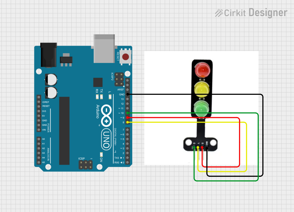
Circuit Documentation
Summary of the Circuit
This circuit consists of an Arduino UNO microcontroller board interfaced with a traffic light module. The traffic light module has three outputs corresponding to the RED, YELLOW, and GREEN lights. The Arduino UNO controls these lights by providing signals to the respective pins on the traffic light module. The ground (GND) pin of the traffic light module is connected to the GND pin of the Arduino UNO to complete the circuit.
Component List
Arduino UNO
- Description: A microcontroller board based on the ATmega328P.
- Pins: UNUSED, IOREF, Reset, 3.3V, 5V, GND, Vin, A0-A5, SCL, SDA, AREF, D0-D13.
- Purpose: Acts as the central controller for the traffic light module, providing logic and timing for the lights.
Traffic Light Module
- Description: A module with three LEDs representing a traffic light system.
- Pins: GND, RED, YELLOW, GREEN.
- Purpose: To display traffic light signals as instructed by the Arduino UNO.
Wiring Details
Arduino UNO
- GND: Connected to the GND pin of the traffic light module.
- D9: Connected to the RED pin of the traffic light module.
- D8: Connected to the YELLOW pin of the traffic light module.
- D10: Connected to the GREEN pin of the traffic light module.
Traffic Light Module
- GND: Connected to the GND pin of the Arduino UNO.
- RED: Connected to pin D9 of the Arduino UNO.
- YELLOW: Connected to pin D8 of the Arduino UNO.
- GREEN: Connected to pin D10 of the Arduino UNO.
Documented Code
The following code is intended for the Arduino UNO microcontroller to control the traffic light module. The code is written in Arduino's sketch format (.ino).
void setup() {
  // Initialize the traffic light control pins as outputs
  pinMode(9, OUTPUT); // RED light control pin
  pinMode(8, OUTPUT); // YELLOW light control pin
  pinMode(10, OUTPUT); // GREEN light control pin
}

void loop() {
  // RED light sequence
  digitalWrite(9, HIGH);   // Turn on RED light
  delay(1000);             // Keep RED light on for 1 second
  digitalWrite(9, LOW);    // Turn off RED light

  // YELLOW light sequence
  digitalWrite(8, HIGH);   // Turn on YELLOW light
  delay(1000);             // Keep YELLOW light on for 1 second
  digitalWrite(8, LOW);    // Turn off YELLOW light

  // GREEN light sequence
  digitalWrite(10, HIGH);  // Turn on GREEN light
  delay(1000);             // Keep GREEN light on for 1 second
  digitalWrite(10, LOW);   // Turn off GREEN light
}
This code sets up the Arduino UNO to control the traffic light module by setting the appropriate pins to output mode and then cycling through the RED, YELLOW, and GREEN lights in the loop function. Each light is turned on for one second before switching to the next light.