
Battery-Powered Raspberry Pi Zero W with MPU-6050 and LCD Display
View and Edit Project In Cirkit Designer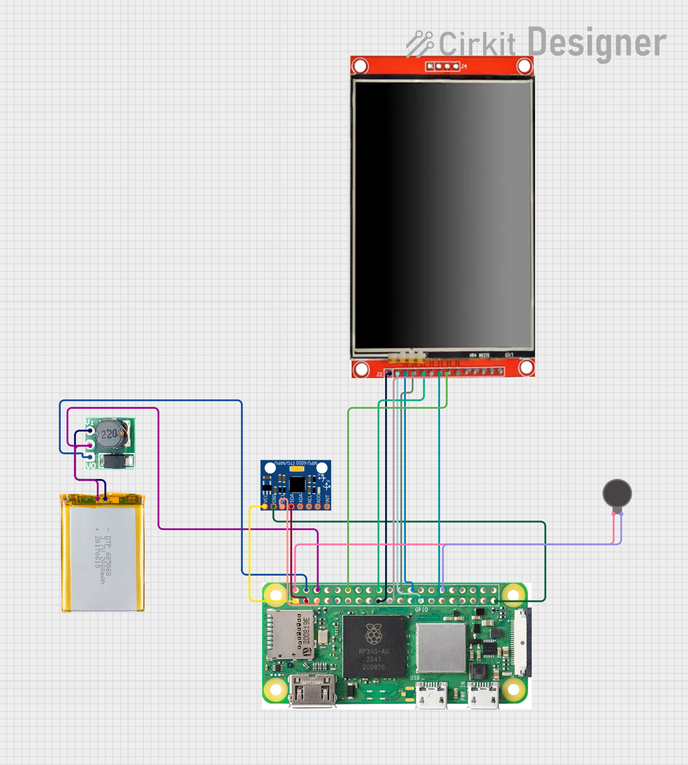
Circuit Documentation
Summary
This document provides a detailed overview of a circuit that includes a 2000mAh Battery, a Step Up Boost converter, a Raspberry Pi Zero W, an MPU-6050 sensor, an LCD TFT screen, and a Vibration Motor. The circuit is designed to power the Raspberry Pi and its peripherals, including the sensor and display, while also providing feedback through a vibration motor.
Component List
2000mAh Battery
- Pins: VCC, GND
- Description: A rechargeable battery providing the primary power source for the circuit.
- Purpose: Supplies power to the Step Up Boost converter.
Step Up Boost 3v-5v
- Pins: Vi, GND, Vo
- Description: A voltage converter that steps up the battery voltage to a stable 5V.
- Purpose: Provides a stable 5V output to power the Raspberry Pi and other components.
Raspberry Pi Zero W
- Pins: 5V, 3V3, GPIO2 (SDA), GPIO 3, GROUND, GPIO 14, GPIO15, GPIO 18, GND, GPIO 23, GPIO24, GPIO 25, GPIO 8, GPIO 7, GPIO 1, GPIO 12, GPIO 16, GPIO 20, GPIO 21, GPIO 04, GPIO 17, GPIO 27, GPIO 22, GPIO 10, GPIO 9, GPIO 11, GPIO 0, GPIO 5, GPIO 6, GPIO 13, GPIO 19, GPIO 26, CSI (CAMERA)
- Description: A small, affordable computer with wireless capabilities.
- Purpose: Acts as the main processing unit for the circuit, interfacing with the sensor, display, and vibration motor.
MPU-6050
- Pins: VCC, GND, SCL, SDA, XDA, XCL, AD0, INT
- Description: A 6-axis motion tracking device.
- Purpose: Provides motion sensing capabilities to the Raspberry Pi.
LCD TFT screen ILI9488 HD
- Pins: PEN, TDO, TDI, VCC (3.3~5V), GND, CS, RST, D/C, SDI(MOSI), SCK, BL, SDO(MISO), TCS, TCK
- Description: A high-definition display screen.
- Purpose: Displays information processed by the Raspberry Pi.
Vibration Motor
- Pins: +, -
- Description: A small motor that provides haptic feedback.
- Purpose: Provides vibration feedback controlled by the Raspberry Pi.
Wiring Details
2000mAh Battery
- VCC is connected to Vi of the Step Up Boost converter.
- GND is connected to GND of the Step Up Boost converter and GROUND of the Raspberry Pi.
Step Up Boost 3v-5v
- Vi is connected to VCC of the 2000mAh Battery.
- GND is connected to GND of the 2000mAh Battery and GROUND of the Raspberry Pi.
- Vo is connected to 5V of the Raspberry Pi.
Raspberry Pi Zero W
- GROUND is connected to GND of the Step Up Boost converter and GND of the 2000mAh Battery.
- 5V is connected to Vo of the Step Up Boost converter and + of the Vibration Motor.
- 3V3 is connected to VCC of the MPU-6050 and VCC (3.3~5V) of the LCD TFT screen.
- GPIO2 (SDA) is connected to SDA of the MPU-6050.
- GPIO 3 is connected to SCL of the MPU-6050.
- GPIO 18 is connected to BL of the LCD TFT screen.
- GPIO24 is connected to D/C of the LCD TFT screen.
- GPIO 25 is connected to RST of the LCD TFT screen.
- GPIO 8 is connected to CS of the LCD TFT screen.
- GPIO 10 is connected to SDI(MOSI) of the LCD TFT screen.
- GPIO 11 is connected to SCK of the LCD TFT screen.
- GND is connected to GND of the LCD TFT screen, GND of the MPU-6050, and - of the Vibration Motor.
MPU-6050
- VCC is connected to 3V3 of the Raspberry Pi.
- GND is connected to GND of the Raspberry Pi.
- SDA is connected to GPIO2 (SDA) of the Raspberry Pi.
- SCL is connected to GPIO 3 of the Raspberry Pi.
LCD TFT screen ILI9488 HD
- VCC (3.3~5V) is connected to 3V3 of the Raspberry Pi.
- GND is connected to GND of the Raspberry Pi.
- BL is connected to GPIO 18 of the Raspberry Pi.
- D/C is connected to GPIO24 of the Raspberry Pi.
- RST is connected to GPIO 25 of the Raspberry Pi.
- CS is connected to GPIO 8 of the Raspberry Pi.
- SDI(MOSI) is connected to GPIO 10 of the Raspberry Pi.
- SCK is connected to GPIO 11 of the Raspberry Pi.
Vibration Motor
- + is connected to 5V of the Raspberry Pi.
- - is connected to GND of the Raspberry Pi.
Code
There is no code provided for this circuit.