Arduino Nano-Based Multi-Channel Volume Controller

Circuit Documentation
Summary
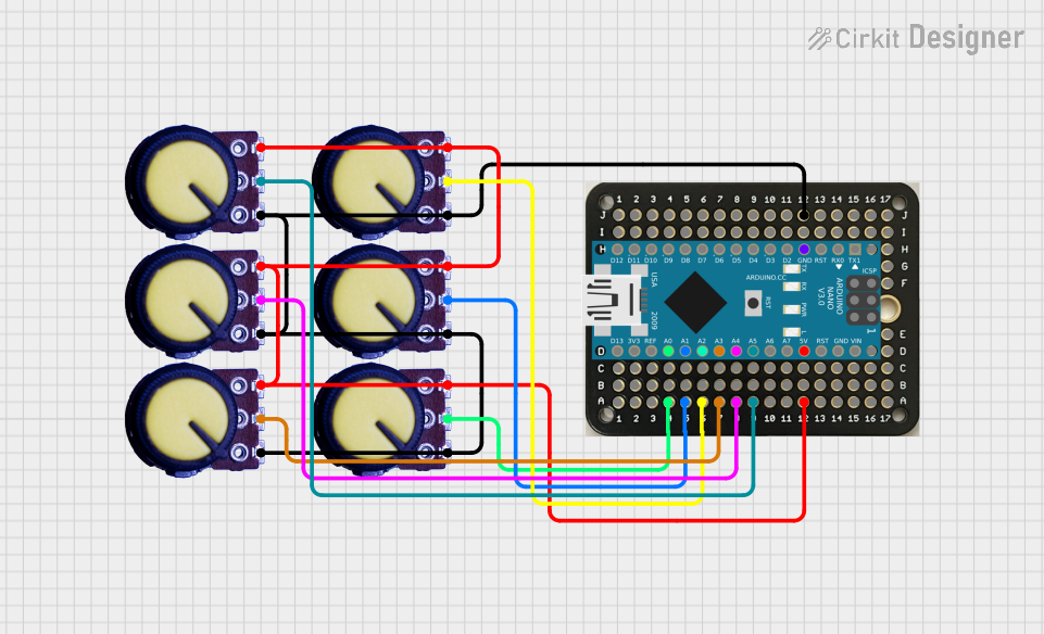
The circuit in question appears to be a multi-channel analog input system using an Arduino Nano as the central processing unit. The system includes several potentiometers that are likely used as variable resistors or sliders to provide analog input to the Arduino Nano. The Arduino Nano reads the analog values from the potentiometers and outputs the data through its serial interface. This setup could be used for applications such as a volume control interface, a mixer panel, or any system requiring multiple analog inputs.
Component List
Potentiometer
- Description: A variable resistor with three terminals: Ground (GND), Output (wiper), and Voltage Supply (VCC).
- Purpose: To provide an adjustable voltage level as an analog input to the Arduino Nano.
Solderable Mini Breadboard
- Description: A compact breadboard with multiple connection points for prototyping electronic circuits.
- Purpose: To facilitate the connections between the potentiometers and the Arduino Nano.
Arduino Nano
- Description: A small, complete, and breadboard-friendly board based on the ATmega328P.
- Purpose: To read analog input values from the potentiometers, process the data, and send it through the serial interface.
Wiring Details
Potentiometers
- GND: Connected to the ground rail on the breadboard.
- Output: Each potentiometer's output is connected to a unique analog input pin on the breadboard, which is then connected to the corresponding analog input on the Arduino Nano.
- VCC: All potentiometers' VCC pins are connected together and to a power rail on the breadboard, which is supplied by the 5V output from the Arduino Nano.
Solderable Mini Breadboard
- A4-A9: Connected to the outputs of the potentiometers.
- A12, D12: Connected to the 5V output from the Arduino Nano.
- D4-D9: Connected to the analog input pins A0-A5 on the Arduino Nano.
- H12, J12: Connected to the GND pin on the Arduino Nano.
Arduino Nano
- 5V: Provides power to the VCC rail on the breadboard and to the potentiometers.
- A0-A5: Analog input pins connected to the potentiometers' outputs.
- GND: Connected to the ground rail on the breadboard.
Documented Code
Arduino Nano Code (Deej_6R.ino)
const int NUM_SLIDERS = 6;
const int analogInputs[NUM_SLIDERS] = {A0, A1, A2, A3, A4, A5};

int analogSliderValues[NUM_SLIDERS];

void setup() {
  for (int i = 0; i < NUM_SLIDERS; i++) {
    pinMode(analogInputs[i], INPUT);
  }

  Serial.begin(9600);
}

void loop() {
  updateSliderValues();
  sendSliderValues(); // Actually send data (all the time)
  // printSliderValues(); // For debug
  delay(10);
}

void updateSliderValues() {
  for (int i = 0; i < NUM_SLIDERS; i++) {
     analogSliderValues[i] = analogRead(analogInputs[i]);
  }
}

void sendSliderValues() {
  String builtString = String("");

  for (int i = 0; i < NUM_SLIDERS; i++) {
    builtString += String((int)analogSliderValues[i]);

    if (i < NUM_SLIDERS - 1) {
      builtString += String("|");
    }
  }

  Serial.println(builtString);
}

void printSliderValues() {
  for (int i = 0; i < NUM_SLIDERS; i++) {
    String printedString = String("Slider #") + String(i + 1) + String(": ") + String(analogSliderValues[i]) + String(" mV");
    Serial.write(printedString.c_str());

    if (i < NUM_SLIDERS - 1) {
      Serial.write(" | ");
    } else {
      Serial.write("\n");
    }
  }
}
Configuration File (config.yaml)
# process names are case-insensitive
# you can use 'master' to indicate the master channel, or a list of process names to create a group
# you can use 'mic' to control your mic input level (uses the default recording device)
# you can use 'deej.unmapped' to control all apps that aren't bound to any slider (this ignores master, system, mic and device-targeting sessions) (experimental)
# windows only - you can use 'deej.current' to control the currently active app (whether full-screen or not) (experimental)
# windows only - you can use a device's full name, i.e. "Speakers (Realtek High Definition Audio)", to bind it. this works for both output and input devices
# windows only - you can use 'system' to control the "system sounds" volume
# important: slider indexes start at 0, regardless of which analog pins you're using!
slider_mapping:
  0: master
  1: firefox.exe
  2:
    - foobar2000.exe
    - spotify.exe
    - iTunes.exe
  3: Discord.exe
  4:
    - Javaw.exe
    - Palworld.exe
  5: deej.unmapped


# set this to true if you want the controls inverted (i.e. top is 0%, bottom is 100%)
invert_sliders: true

# settings for connecting to the arduino board
com_port: COM10
baud_rate: 9600

# adjust the amount of signal noise reduction depending on your hardware quality
# supported values are "low" (excellent hardware), "default" (regular hardware) or "high" (bad, noisy hardware)
noise_reduction: default
This documentation provides an overview of the circuit, including the components used, their wiring, and the code that operates the microcontroller. The code is responsible for reading the analog values from the potentiometers and sending them over the serial interface, potentially to be used by a software application for controlling various parameters.