
Multi-Channel Load Cell Measurement System with JYS60 Amplifiers and DAQ Integration
View and Edit Project In Cirkit Designer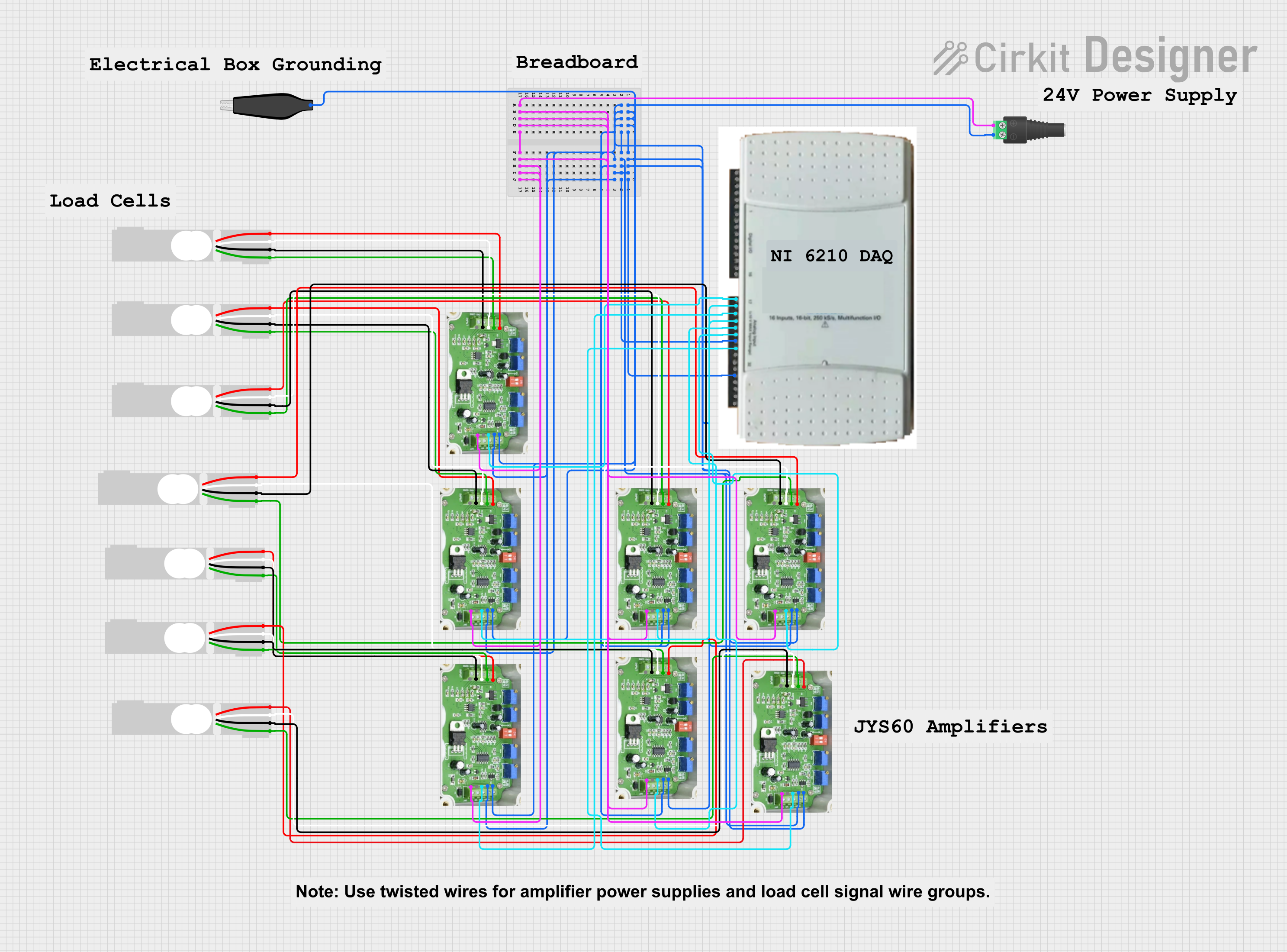
Circuit Documentation
Summary
The circuit in question appears to be designed for signal amplification and data acquisition from multiple load cells. It includes a power supply input through a 2.1mm Barrel Jack with Terminal Block, several JYS60 Amplifiers for signal conditioning, multiple Load Cells as the primary sensors, a Data Acquisition System (DAQ) for capturing the conditioned signals, and an AdaGator Side Black component for grounding purposes.
Component List
2.1mm Barrel Jack with Terminal Block
- Description: This component provides a connection point for an external power supply.
- Pins: POS (Positive), NEG (Negative)
JYS60 Amplifier
- Description: An amplifier used for conditioning the signal from the load cells.
- Pins: E+ (Excitation Positive), S+ (Signal Positive), S- (Signal Negative), GND (Ground), GNDD (Digital Ground), VO (Voltage Output), IO (Current Output), 24V (Power Supply)
Load Cell - Red/white/black/green
- Description: A transducer that converts force into an electrical signal.
- Pins: E+ (Excitation Positive), A- (Signal Negative), E- (Excitation Negative), A+ (Signal Positive)
DAQ
- Description: Data Acquisition System used for capturing and digitizing analog signals from the amplifiers.
- Pins: 32 pins for various I/O connections.
AdaGator Side Black
- Description: A component used for grounding.
- Pins: wire (Ground connection)
Comment
- Description: A placeholder for comments within the circuit design, not an actual physical component.
- Pins: None
Wiring Details
2.1mm Barrel Jack with Terminal Block
- POS connected to 24V of all JYS60 Amplifiers
- NEG connected to GND and GNDD of all JYS60 Amplifiers and AdaGator Side Black wire
JYS60 Amplifiers
- E+ connected to E+ of corresponding Load Cell
- S+ connected to A+ of corresponding Load Cell
- S- connected to A- of corresponding Load Cell
- GND connected to E- of corresponding Load Cell and NEG of Barrel Jack
- GNDD connected to AdaGator Side Black wire and NEG of Barrel Jack
- VO connected to specific pins on the DAQ (17, 18, 19, 20, 21, 22, 23, 24)
- IO not connected
- 24V connected to POS of Barrel Jack
Load Cells
- E+ connected to E+ of corresponding JYS60 Amplifier
- A- connected to S- of corresponding JYS60 Amplifier
- E- connected to GND of corresponding JYS60 Amplifier
- A+ connected to S+ of corresponding JYS60 Amplifier
DAQ
- Pins 17, 18, 19, 20, 21, 22, 23, 24 connected to VO of corresponding JYS60 Amplifiers
AdaGator Side Black
- wire connected to GNDD and GND of all JYS60 Amplifiers and NEG of Barrel Jack
Documented Code
No code has been provided for any microcontrollers in the circuit. If there are any embedded systems or programmable components involved in this circuit, the code for those should be documented here. Since no code is available, this section remains empty.