
ESP8266 NodeMCU Controlled NRF24L01 Wireless Communication Module
View and Edit Project In Cirkit Designer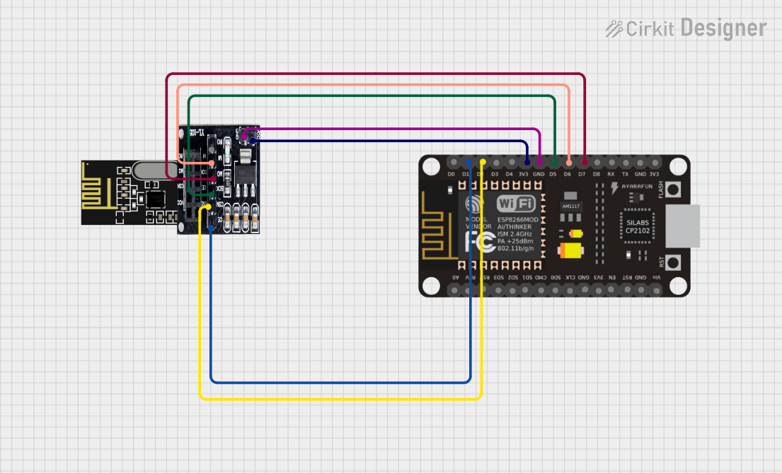
Circuit Documentation
Summary
This circuit integrates an NRF24L01 transceiver module with an NRF24L01 Adapter and an ESP8266 NodeMCU microcontroller. The purpose of this circuit is to enable wireless communication capabilities for the ESP8266 NodeMCU using the NRF24L01 module. The NRF24L01 Adapter is used to facilitate the connection between the NRF24L01 module and the ESP8266 NodeMCU, providing the necessary voltage level translation and pin access.
Component List
NRF24L01 Transceiver Module
- Description: A 2.4 GHz wireless transceiver module.
- Pins: IRQ (not used), MOSI, CSN, VCC (3V), GND, CE, SCK, MISO.
NRF24L01 Adapter
- Description: An adapter board for the NRF24L01 module, providing voltage regulation and breakout pins.
- Pins: CE, CSN, SCK, MOSI, MISO, IRQ, VCC, GND.
ESP8266 NodeMCU
- Description: A Wi-Fi enabled microcontroller board based on the ESP8266 chipset.
- Pins: D0, D1, D2, D3, D4, 3V3, GND, D5, D6, D7, D8, RX, TX, A0, RSV, SD3, SD2, SD1, CMD, SD0, CLK, EN, RST, VIN.
Wiring Details
NRF24L01 Transceiver Module
- IRQ (not used): Not connected.
- MOSI: Connected to MOSI on NRF24L01 Adapter.
- CSN: Connected to CSN on NRF24L01 Adapter.
- VCC (3V): Connected to VCC on NRF24L01 Adapter.
- GND: Connected to GND on NRF24L01 Adapter.
- CE: Connected to CE on NRF24L01 Adapter.
- SCK: Connected to SCK on NRF24L01 Adapter.
- MISO: Connected to MISO on NRF24L01 Adapter.
NRF24L01 Adapter
- CE: Connected to D1 on ESP8266 NodeMCU.
- CSN: Connected to D2 on ESP8266 NodeMCU.
- SCK: Connected to D5 on ESP8266 NodeMCU.
- MOSI: Connected to D7 on ESP8266 NodeMCU.
- MISO: Connected to D6 on ESP8266 NodeMCU.
- IRQ: Not connected.
- VCC: Connected to 3V3 on ESP8266 NodeMCU.
- GND: Connected to GND on ESP8266 NodeMCU.
ESP8266 NodeMCU
- D1: Connected to CE on NRF24L01 Adapter.
- D2: Connected to CSN on NRF24L01 Adapter.
- D5: Connected to SCK on NRF24L01 Adapter.
- D7: Connected to MOSI on NRF24L01 Adapter.
- D6: Connected to MISO on NRF24L01 Adapter.
- 3V3: Connected to VCC on NRF24L01 Adapter.
- GND: Connected to GND on NRF24L01 Adapter.
- Other pins are not used in this circuit.
Documented Code
No code has been provided for the microcontroller. The documentation of the code would typically include the setup and loop functions for an Arduino-based microcontroller like the ESP8266 NodeMCU, along with any necessary functions to handle the communication with the NRF24L01 module. This would involve initializing the SPI interface and configuring the NRF24L01 module for transmission or reception of data.