
ESP32-Based Health Monitoring System with MAX30100 and I2C LCD
View and Edit Project In Cirkit Designer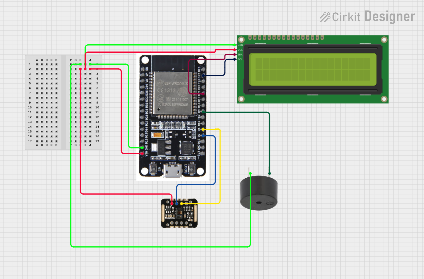
Circuit Documentation
Summary
This document provides a detailed overview of a circuit that includes an ESP32 microcontroller, a MAX30100 pulse oximeter sensor, a 16x2 I2C LCD display, and a buzzer. The circuit is designed to measure and display pulse and oxygen levels, and it includes an alert mechanism using a buzzer.
Component List
MAX30100
- Description: Pulse oximeter and heart-rate sensor.
- Pins: VIN, SDA, SCL, GND, RD, IRD, INT
ESP32
- Description: Microcontroller with Wi-Fi and Bluetooth capabilities.
- Pins: EN, VP, VN, D34, D35, D32, D33, D25, D26, D27, D14, D12, D13, GND, VIN, 3V3, D15, D2, D4, RX2, TX2, D5, D18, D19, D21, RX0, TX0, D22, D23, BOOT
16x2 I2C LCD
- Description: 16x2 character LCD display with I2C interface.
- Pins: GND, VCC, SDA, SCL
Buzzer
- Description: Simple piezoelectric buzzer.
- Pins: PIN, GND
Wiring Details
MAX30100
- VIN: Connected to ESP32 VIN
- SDA: Connected to ESP32 D2
- SCL: Connected to ESP32 D4
- GND: Connected to ESP32 GND
ESP32
- GND: Connected to Buzzer GND, 16x2 I2C LCD GND
- VIN: Connected to MAX30100 VIN, 16x2 I2C LCD VCC
- D2: Connected to MAX30100 SDA
- D4: Connected to MAX30100 SCL
- D5: Connected to Buzzer PIN
- D21: Connected to 16x2 I2C LCD SDA
- D22: Connected to 16x2 I2C LCD SCL
16x2 I2C LCD
- GND: Connected to ESP32 GND
- VCC: Connected to ESP32 VIN
- SDA: Connected to ESP32 D21
- SCL: Connected to ESP32 D22
Buzzer
- PIN: Connected to ESP32 D5
- GND: Connected to ESP32 GND
Code
No code is provided for this circuit.
This documentation provides a comprehensive overview of the circuit, including a summary, component list, wiring details, and code section. Each component is described, and the wiring details ensure proper connections for the circuit to function as intended.