
Battery-Powered Arduino and ESP32 Controlled Servo System with BMS and TP4056 Charging
View and Edit Project In Cirkit Designer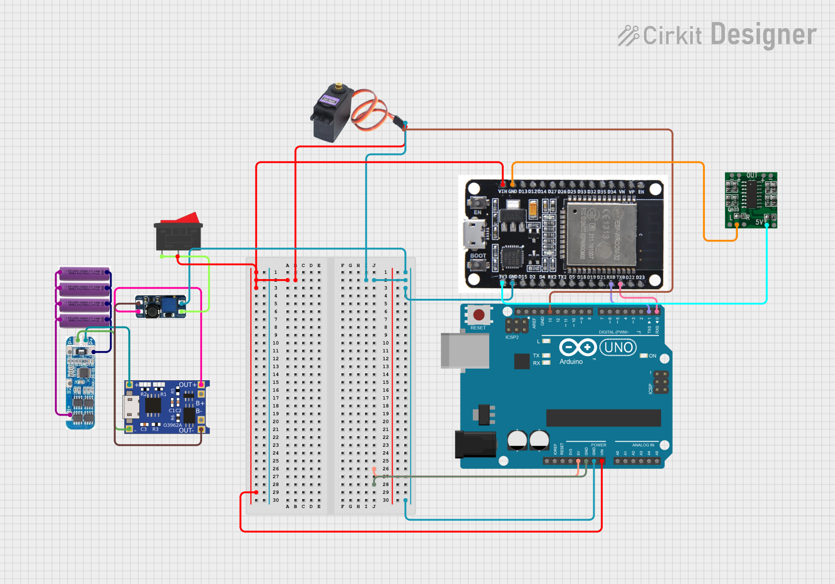
Circuit Documentation
Summary
This document provides a detailed overview of a circuit that includes various components such as batteries, a Battery Management System (BMS), a TP4056 charger module, a DC-DC boost converter, an Arduino UNO, an ESP32, a servo motor, a rocker switch, and a PAM8403 amplifier. The circuit is designed to manage power distribution, control a servo motor, and amplify audio signals.
Component List
3.7v Battery
- Pins: +, -
- Description: Provides power to the circuit.
- Purpose: Power source.
BMS (Battery Management System)
- Pins: B+, B2, B1, B-, P-, P+
- Description: Manages the charging and discharging of the batteries.
- Purpose: Battery management.
TP4056
- Pins: OUT-, B-, B+, OUT+, IN-, IN+
- Description: Lithium-ion battery charger module.
- Purpose: Charging the batteries.
DC-DC Boost Converter
- Pins: VIN-, VIN+, VOUT+, VOUT-
- Description: Boosts the voltage from the battery to a higher level.
- Purpose: Voltage conversion.
Arduino UNO
- Pins: UNUSED, IOREF, Reset, 3.3V, 5V, GND, Vin, A0, A1, A2, A3, A4, A5, SCL, SDA, AREF, D13, D12, D11, D10, D9, D8, D7, D6, D5, D4, D3, D2, D1, D0
- Description: Microcontroller board.
- Purpose: Control and processing.
ESP32
- Pins: EN, VP, VN, D34, D35, D32, D33, D25, D26, D27, D14, D12, D13, GND, VIN, 3V3, D15, D2, D4, RX2, TX2, D5, D18, D19, D21, RX0, TX0, D22, D23, BOOT
- Description: Wi-Fi and Bluetooth microcontroller.
- Purpose: Wireless communication and control.
MG996R (Servo Motor)
- Pins: GND, VCC, SIG
- Description: High-torque servo motor.
- Purpose: Actuation.
Rocker Switch
- Pins: 1, 2
- Description: On/Off switch.
- Purpose: Power control.
PAM8403
- Pins: 5vIN+, GND/IN-, R-INPUT, GND, L-INPUT, L-, L+, R+, R-
- Description: 3W stereo audio amplifier.
- Purpose: Audio amplification.
Wiring Details
3.7v Battery
- + Pin: Connected to B+ pin of BMS.
- - Pin: Connected to B- pin of BMS.
BMS
- B+ Pin: Connected to + pin of all 3.7v batteries.
- B- Pin: Connected to - pin of all 3.7v batteries.
- P- Pin: Connected to IN- pin of TP4056.
- P+ Pin: Connected to IN+ pin of TP4056.
TP4056
- IN- Pin: Connected to P- pin of BMS.
- IN+ Pin: Connected to P+ pin of BMS.
- OUT- Pin: Connected to VIN- pin of DC-DC Boost Converter.
- OUT+ Pin: Connected to VIN+ pin of DC-DC Boost Converter.
DC-DC Boost Converter
- VIN- Pin: Connected to OUT- pin of TP4056.
- VIN+ Pin: Connected to OUT+ pin of TP4056.
- VOUT- Pin: Connected to GND pin of MG996R, GND pin of ESP32, and GND pin of Arduino UNO.
- VOUT+ Pin: Connected to pin 1 of Rocker Switch.
Rocker Switch
- Pin 1: Connected to VOUT+ pin of DC-DC Boost Converter.
- Pin 2: Connected to VCC pin of MG996R, VIN pin of ESP32, and Vin pin of Arduino UNO.
Arduino UNO
- Vin Pin: Connected to pin 2 of Rocker Switch.
- GND Pin: Connected to VOUT- pin of DC-DC Boost Converter.
- D13 Pin: Connected to SIG pin of MG996R.
- D1 Pin: Connected to RX0 pin of ESP32.
- D0 Pin: Connected to TX0 pin of ESP32.
ESP32
- VIN Pin: Connected to pin 2 of Rocker Switch.
- GND Pin: Connected to VOUT- pin of DC-DC Boost Converter.
- RX0 Pin: Connected to D1 pin of Arduino UNO.
- TX0 Pin: Connected to D0 pin of Arduino UNO.
- 3V3 Pin: Connected to 5vIN+ pin of PAM8403.
MG996R (Servo Motor)
- GND Pin: Connected to VOUT- pin of DC-DC Boost Converter.
- VCC Pin: Connected to pin 2 of Rocker Switch.
- SIG Pin: Connected to D13 pin of Arduino UNO.
PAM8403
- GND Pin: Connected to GND pin of ESP32.
- 5vIN+ Pin: Connected to 3V3 pin of ESP32.
Documented Code
Arduino UNO Code (sketch.ino)
void setup() {
  // put your setup code here, to run once:

}

void loop() {
  // put your main code here, to run repeatedly:

}
Additional Documentation (documentation.txt)
This document provides a comprehensive overview of the circuit, including a summary, component list, wiring details, and documented code. Each component is described, and its connections are detailed to ensure clarity and ease of understanding.