
Arduino UNO Based IR Object Detection with OV7670 Camera Interface
View and Edit Project In Cirkit Designer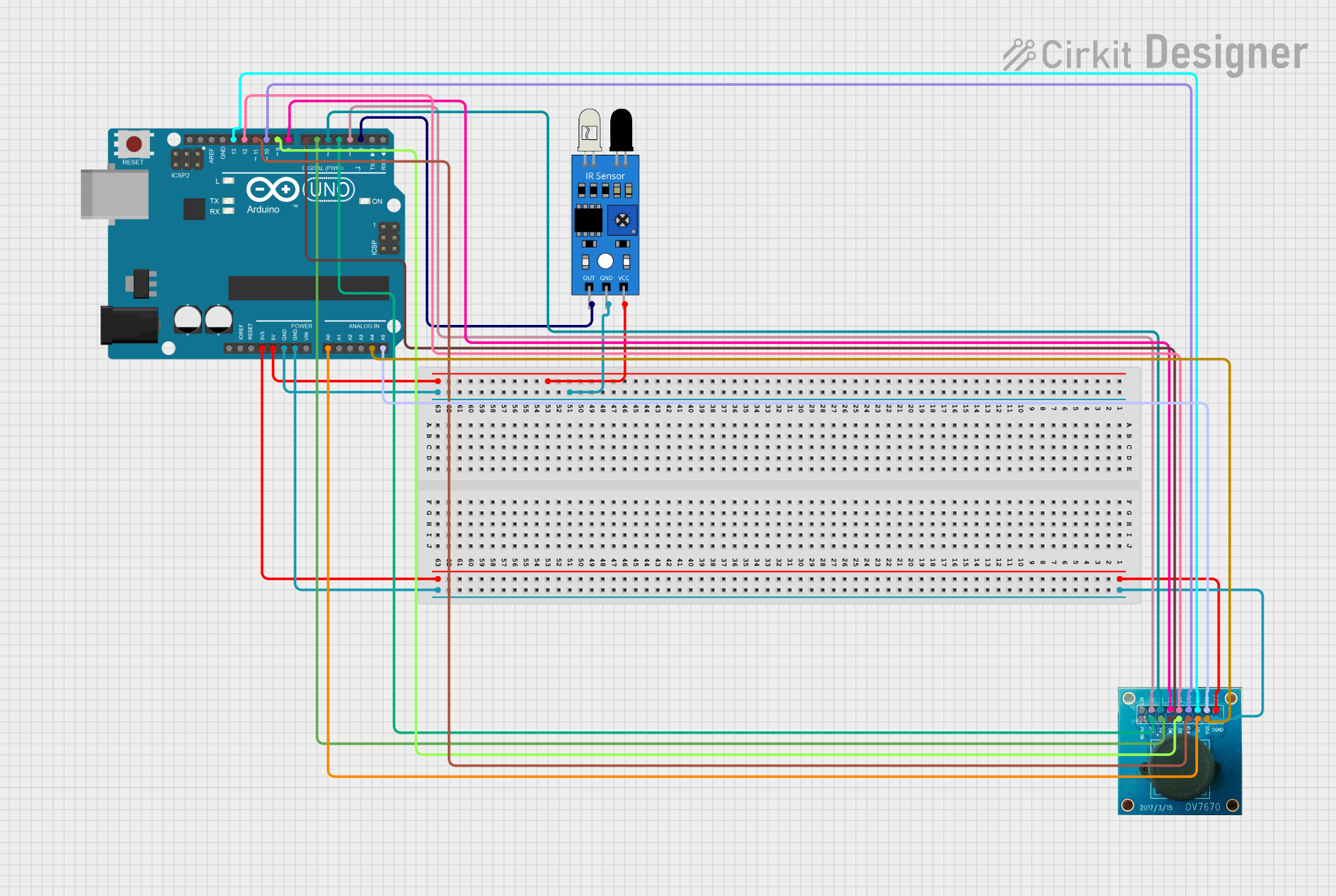
Circuit Documentation
Summary
The circuit consists of an Arduino UNO microcontroller, an infrared (IR) sensor, and an OV7670 camera module. The Arduino UNO serves as the central processing unit, interfacing with the IR sensor for detecting objects and the OV7670 camera module for capturing images. The IR sensor is powered by the Arduino's 5V output and communicates with the Arduino via a digital input. The OV7670 camera module is connected to the Arduino for both power (3.3V) and data transfer, utilizing digital pins for image data and synchronization signals, as well as analog pins for the I2C communication used to configure the camera.
Component List
Arduino UNO
- Microcontroller board based on the ATmega328P
- Features digital I/O pins, analog input pins, and various power outputs
- Utilized for controlling the IR sensor and OV7670 camera module
IR Sensor
- Sensor for detecting objects within a certain range
- Outputs a digital signal to the Arduino when an object is detected
- Powered by the Arduino's 5V output
OV7670 Camera Module
- A low-voltage CMOS image sensor that provides the functionality of a single-chip VGA camera
- Interfaces with the Arduino for image capture and configuration
- Powered by the Arduino's 3.3V output
Wiring Details
Arduino UNO
- 3.3V supplies power to the OV7670 camera module
- 5V supplies power to the IR sensor
- GND is connected to the ground pins of both the IR sensor and OV7670 camera module
- A0 is connected to the OV7670's HS (HREF) signal
- A4 (SDA) is connected to the OV7670's SDA for I2C communication
- A5 (SCL) is connected to the OV7670's SCL for I2C communication
- D2 is connected to the IR sensor's output
- D3-D13 are connected to the OV7670's data pins (D0-D7) and synchronization signals (VS, HS, PLK, XLK)
IR Sensor
- out sends a digital signal to the Arduino's D2 pin when an object is detected
- gnd is connected to the Arduino's GND
- vcc is connected to the Arduino's 5V
OV7670 Camera Module
- 3.3V receives power from the Arduino's 3.3V output
- DGND is connected to the Arduino's GND
- D0-D7 are connected to the Arduino's D3-D10 for image data transfer
- PLK is connected to the Arduino's D10
- XLK is connected to the Arduino's D11
- VS is connected to the Arduino's D13 for vertical sync signal
- HS is connected to the Arduino's A0 for horizontal reference signal
- SCL is connected to the Arduino's A5 for I2C clock
- SDA is connected to the Arduino's A4 for I2C data
Documented Code
Arduino UNO Code (sketch.ino)
void setup() {
  // put your setup code here, to run once:

}

void loop() {
  // put your main code here, to run repeatedly:

}
This code is a template for the Arduino UNO and does not contain any specific functionality. It provides the basic structure for an Arduino sketch with setup() and loop() functions. The setup() function is intended for initialization code that runs once when the program starts, and the loop() function contains code that runs continuously.
Additional Notes
- The provided code for the Arduino UNO is a placeholder and needs to be populated with the logic for interfacing with the IR sensor and OV7670 camera module.
- The IR sensor's output is connected to the Arduino's D2 pin, which should be configured as an input in the
setup()function. - The OV7670 camera module requires additional code for initialization and capturing images, which should be implemented in the
setup()andloop()functions, respectively. - The I2C communication with the OV7670's SDA and SCL pins will require the use of the
Wirelibrary in the Arduino code.