Cirkit Designer
Your all-in-one circuit design IDE
Home /
Project Documentation
ESP32 and Arduino UNO Based Gas Detection System with LED Indicator and I2C LCD Display
Circuit Documentation
Summary of the Circuit
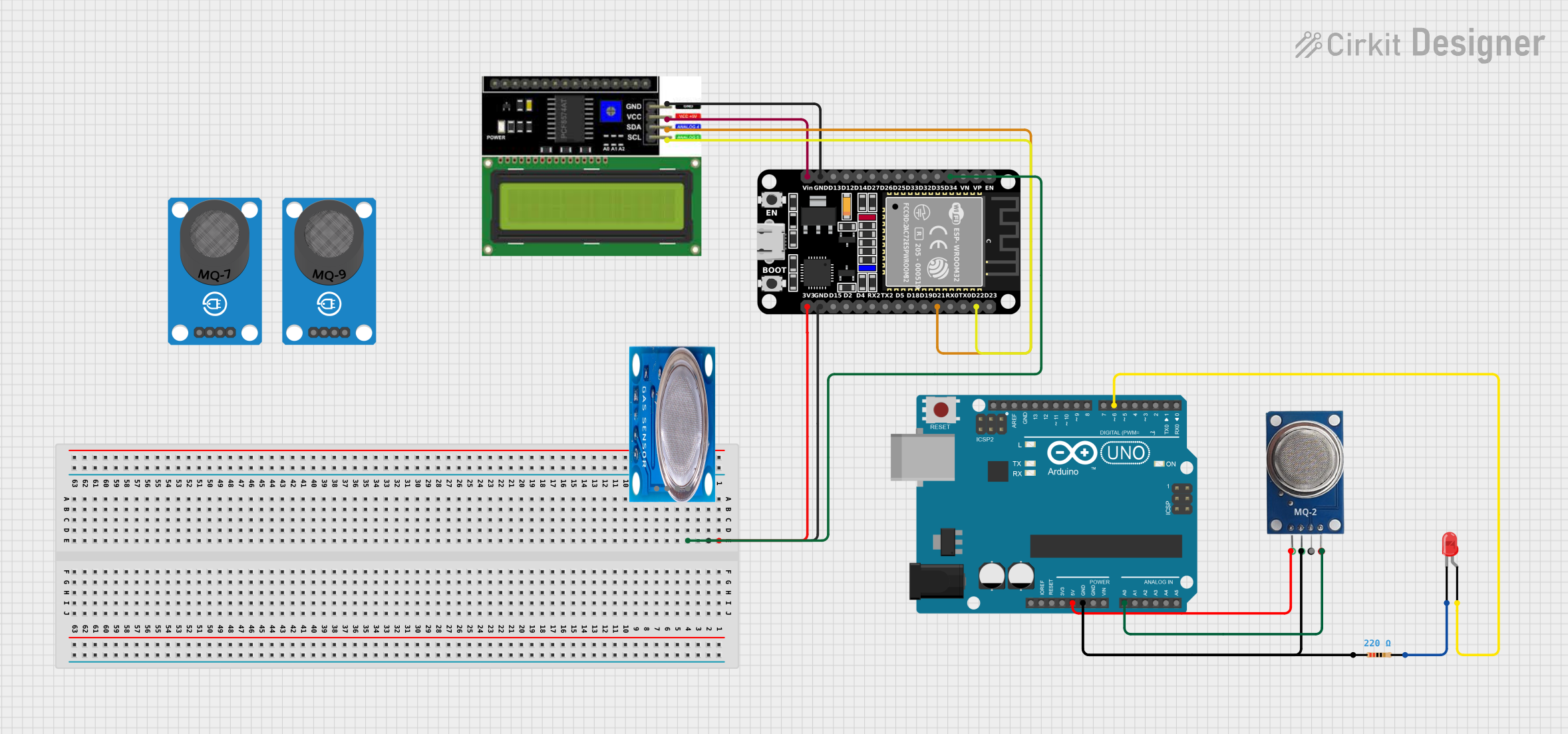
This circuit is designed to monitor gas levels using an MQ-2 sensor and provide a visual indication of the gas concentration through the brightness of an LED. The circuit utilizes an Arduino UNO microcontroller to read the analog output from the MQ-2 sensor, process the data, and control the LED brightness accordingly. Additionally, the circuit includes an ESP32 microcontroller connected to an LCD I2C display for potential data display purposes.
Component List
LED: Two Pin (red)
- Description: A red LED used as a visual indicator.
- Pins: cathode, anode
Resistor
- Description: A resistor with a resistance value of 220 Ohms.
- Pins: pin1, pin2
ESP32 (30 pin)
- Description: A microcontroller with Wi-Fi and Bluetooth capabilities.
- Pins: EN, VP, VN, D34, D35, D32, D33, D25, D26, D27, D14, D12, D13, GND, Vin, D23, D22, TX0, RX0, D21, D19, D18, D5, TX2, RX2, D4, D2, D15, 3V3
MQ-2
- Description: A gas sensor for detecting LPG, propane, hydrogen, and other combustible gases.
- Pins: Vcc, GND, DO, AO
MQ-5
- Description: A gas sensor for detecting natural gas and liquefied gas.
- Pins: VCC, GND, Digi Out, Analog out
MQ-7 Breakout
- Description: A carbon monoxide (CO) gas sensor.
- Pins: VCC, GND, DO, AO
MQ-9 Breakout
- Description: A sensor for detecting carbon monoxide and flammable gases.
- Pins: VCC, GND, DO, AO
Arduino UNO
- Description: A microcontroller board based on the ATmega328P.
- Pins: UNUSED, IOREF, Reset, 3.3V, 5V, GND, Vin, A0, A1, A2, A3, A4, A5, SCL, SDA, AREF, D13, D12, D11, D10, D9, D8, D7, D6, D5, D4, D3, D2, D1, D0
LCD I2C Display
- Description: A liquid crystal display with an I2C interface for displaying data.
- Pins: GND, VCC, SDA, SCL
Wiring Details
LED: Two Pin (red)
- Anode: Connected to Arduino UNO pin D6
- Cathode: Connected to one end of the Resistor
Resistor
- Pin1: Connected to MQ-2 GND
- Pin2: Connected to LED cathode
ESP32 (30 pin)
- 3V3: Not connected
- GND: Connected to LCD I2C Display GND
- Vin: Connected to LCD I2C Display VCC
- D22: Connected to LCD I2C Display SCL
- D21: Connected to LCD I2C Display SDA
MQ-2
- Vcc: Connected to Arduino UNO 5V
- GND: Connected to one end of the Resistor
- AO: Connected to Arduino UNO pin A0
Arduino UNO
- 5V: Connected to MQ-2 Vcc
- GND: Connected to one end of the Resistor
- A0: Connected to MQ-2 AO
- D6: Connected to LED anode
LCD I2C Display
- GND: Connected to ESP32 GND
- VCC: Connected to ESP32 Vin
- SDA: Connected to ESP32 D21
- SCL: Connected to ESP32 D22
Documented Code
Arduino UNO Code for MQ-2 Sensor Reading with LED Indicator
/*
  MQ-2 Sensor Reading with LED Indicator
  This sketch reads analog data from an MQ-2 gas sensor connected to pin A0.
  It maps the sensor's 10-bit analog output to an 8-bit range and uses this
  value to control the brightness of an LED connected to pin D6 using PWM.
  The LED's brightness is directly proportional to the sensor's reading.
  The serial monitor outputs the sensor's analog value every 500 milliseconds.
*/

// Sensor pins: D6 for LED output, A0 for analog input from MQ-2 sensor
#define ledPin 6
#define sensorPin A0

void setup() {
  Serial.begin(9600); // Initialize serial communication at 9600 baud rate
  pinMode(ledPin, OUTPUT); // Set the LED pin as an output
  digitalWrite(ledPin, LOW); // Ensure the LED is off when starting
}

void loop() {
  int sensorValue = readSensor(); // Read the sensor value
  Serial.print("Analog output: "); // Print a message to the serial monitor
  Serial.println(sensorValue); // Print the sensor value to the serial monitor
  delay(500); // Wait for half a second before reading the sensor again
}

// This function reads the analog value from the sensor and maps it to a range suitable for PWM
int readSensor() {
  unsigned int sensorValue = analogRead(sensorPin); // Read the analog value from sensor
  unsigned int outputValue = map(sensorValue, 0, 1023, 0, 255); // Map the 10-bit data to 8-bit data

  // Use the mapped value to set the brightness of the LED
  analogWrite(ledPin, outputValue);

  return sensorValue; // Return the original analog value
}
This code is designed to be uploaded to the Arduino UNO microcontroller. It reads the analog output from the MQ-2 sensor, maps the value to an 8-bit range, and adjusts the LED brightness accordingly. The sensor value is also printed to the serial monitor every 500 milliseconds.