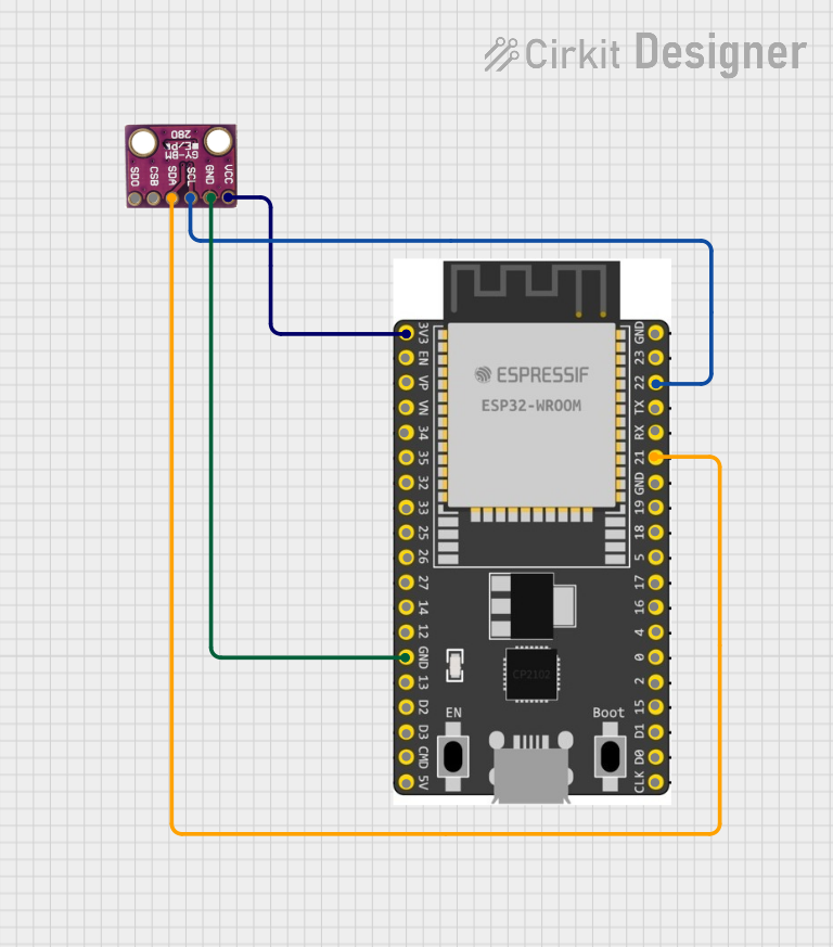
ESP32-Based BMP280 Barometric Pressure Sensor Interface

Circuit Documentation
Summary of the Circuit
This circuit integrates an ESP32 Wroom Dev Kit microcontroller with a BMP280 sensor. The ESP32 serves as the central processing unit, capable of Wi-Fi and Bluetooth communication, while the BMP280 provides temperature and barometric pressure measurements. The circuit is designed to read environmental data from the BMP280 sensor and process it using the ESP32. The power supply for the BMP280 sensor is drawn from the ESP32's 3.3V output, and the sensor communicates with the ESP32 via the I2C protocol.
Component List
ESP 32 Wroom Dev Kit
- Description: A powerful microcontroller with Wi-Fi and Bluetooth capabilities, suitable for a wide range of IoT applications.
- Pins: 3V3, EN, VP, VN, GPIO 34, GPIO 35, GPIO 32, GPIO 33, GPIO 25, GPIO 26, GPIO 27, GPIO 14, GND, GPIO 13, SD2, SD3, CMD, V5, GPIO 23, GPIO 22, TXD, RXD, GPIO 21, GPIO 19, GPIO 18, GPIO 5, GPIO 17, GPIO 16, GPIO 4, GPIO 0, GPIO 2, GPIO 15, SD1, SD0, CLK
BMP280
- Description: A digital barometric pressure and temperature sensor with high accuracy and low power consumption.
- Pins: SDO, CSB, SDA, SCL, GND, VCC
Wiring Details
ESP 32 Wroom Dev Kit
- 3V3 connected to BMP280 VCC
- GND connected to BMP280 GND
- GPIO 22 (SCL) connected to BMP280 SCL
- GPIO 21 (SDA) connected to BMP280 SDA
BMP280
- VCC connected to ESP32 3V3
- GND connected to ESP32 GND
- SCL connected to ESP32 GPIO 22
- SDA connected to ESP32 GPIO 21
Documented Code
No code has been provided for the microcontroller. To fully utilize the circuit, embedded code should be written to initialize and read data from the BMP280 sensor over the I2C interface, process the data as required, and perform any necessary actions such as logging the data, sending it over Wi-Fi or Bluetooth, or displaying it on a user interface.
Typically, the code would include the following steps:
- Initialize I2C communication on the ESP32.
- Configure the BMP280 sensor settings.
- Read sensor data at regular intervals.
- Process and use the data as needed.
Since no code is provided, this section will remain empty until the appropriate code is developed and documented.