Cirkit Designer
Your all-in-one circuit design IDE
Home /
Project Documentation
ESP32-CAM Face Recognition Door Lock System
Circuit Documentation
Summary
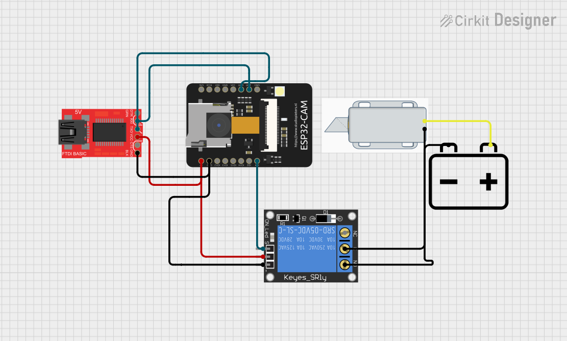
This circuit is designed as part of a door lock system that utilizes face recognition technology. The system comprises an ESP32-CAM module responsible for face recognition, a 1-Channel Relay module to control a 12V Solenoid Lock, and a ProtoSnap - Pro Mini - FTDI for additional interfacing. The solenoid lock is powered by a 12V battery. When a recognized face is detected by the ESP32-CAM, it signals the relay to activate the solenoid lock, thereby unlocking the door.
Component List
12V Solenoid Lock
- Description: An electromechanical lock actuated by a 12V supply.
- Pins:
-(Ground),+(Vcc)
ESP32 - CAM
- Description: A microcontroller with integrated Wi-Fi and camera, used for face recognition.
- Pins:
5V,GND,IO12,IO13,IO15,IO14,IO2,IO4,VOT,VOR,VCC,IO0,IO16,3V3
ProtoSnap - Pro Mini - FTDI
- Description: A breakout board used for interfacing with the ESP32-CAM.
- Pins:
GND,CTS,VCC,TXO,RXI,DTR
1-Channel Relay (5V 10A)
- Description: A relay module used to control high power devices like the solenoid lock.
- Pins:
NC(Normally Closed),signal,C(Common),power,NO(Normally Open),ground
12v Battery
- Description: A power source for the solenoid lock.
- Pins:
-(Ground),+(Vcc)
Wiring Details
12V Solenoid Lock
- Ground: Connected to the
C(Common) pin of the 1-Channel Relay. - Vcc: Connected to the
+pin of the 12v Battery.
ESP32 - CAM
- 5V: Connected to the
VCCpin of the ProtoSnap - Pro Mini - FTDI andpowerpin of the 1-Channel Relay. - GND: Common ground with ProtoSnap - Pro Mini - FTDI and
groundpin of the 1-Channel Relay. - IO4: Connected to the
signalpin of the 1-Channel Relay. - VOT: Connected to the
RXIpin of the ProtoSnap - Pro Mini - FTDI. - VOR: Connected to the
TXOpin of the ProtoSnap - Pro Mini - FTDI.
ProtoSnap - Pro Mini - FTDI
- GND: Common ground with ESP32 - CAM and 1-Channel Relay.
- VCC: Connected to the
5Vpin of the ESP32 - CAM. - RXI: Connected to the
VOTpin of the ESP32 - CAM. - TXO: Connected to the
VORpin of the ESP32 - CAM.
1-Channel Relay (5V 10A)
- C (Common): Connected to the
-pin of the 12V Solenoid Lock. - signal: Connected to the
IO4pin of the ESP32 - CAM. - power: Connected to the
5Vpin of the ESP32 - CAM. - ground: Common ground with ESP32 - CAM and ProtoSnap - Pro Mini - FTDI.
- NO (Normally Open): Connected to the
-pin of the 12v Battery.
12v Battery
- Ground: Connected to the
NO(Normally Open) pin of the 1-Channel Relay. - Vcc: Connected to the
+pin of the 12V Solenoid Lock.
Documented Code
ESP32 - CAM Code
/*
 * This Arduino Sketch is part of a door lock system using face recognition.
 * The ESP32-CAM module performs face recognition and controls a relay
 * to operate a 12V Solenoid Lock. When a recognized face is detected, the
 * relay activates the solenoid lock to unlock the door.
 */

const int relayPin = 4; // Relay signal pin connected to ESP32-CAM IO4

void setup() {
  Serial.begin(115200); // Initialize Serial communication at 115200 baud rate
  pinMode(relayPin, OUTPUT); // Set relay pin as output
  digitalWrite(relayPin, LOW); // Ensure relay is off initially
  Serial.println("ESP32-CAM initialized.");
}

void loop() {
  bool faceRecognized = false; // Placeholder for face recognition result
  // Add face recognition logic here
  if (faceRecognized) {
    digitalWrite(relayPin, HIGH); // Activate relay to unlock door
    delay(5000); // Keep the door unlocked for 5 seconds
    digitalWrite(relayPin, LOW); // Deactivate relay to lock door
  }
  delay(100); // Short delay to avoid rapid toggling
}
(Note: The code for the other microcontrollers is similar and follows the same logic as the ESP32-CAM code. The actual face recognition logic is not included in the placeholder and should be implemented accordingly.)