Cirkit Designer
Your all-in-one circuit design IDE
Home /
Project Documentation
Arduino UNO-Based Smart Home Automation System with Flame and IR Sensors
Circuit Documentation
Summary
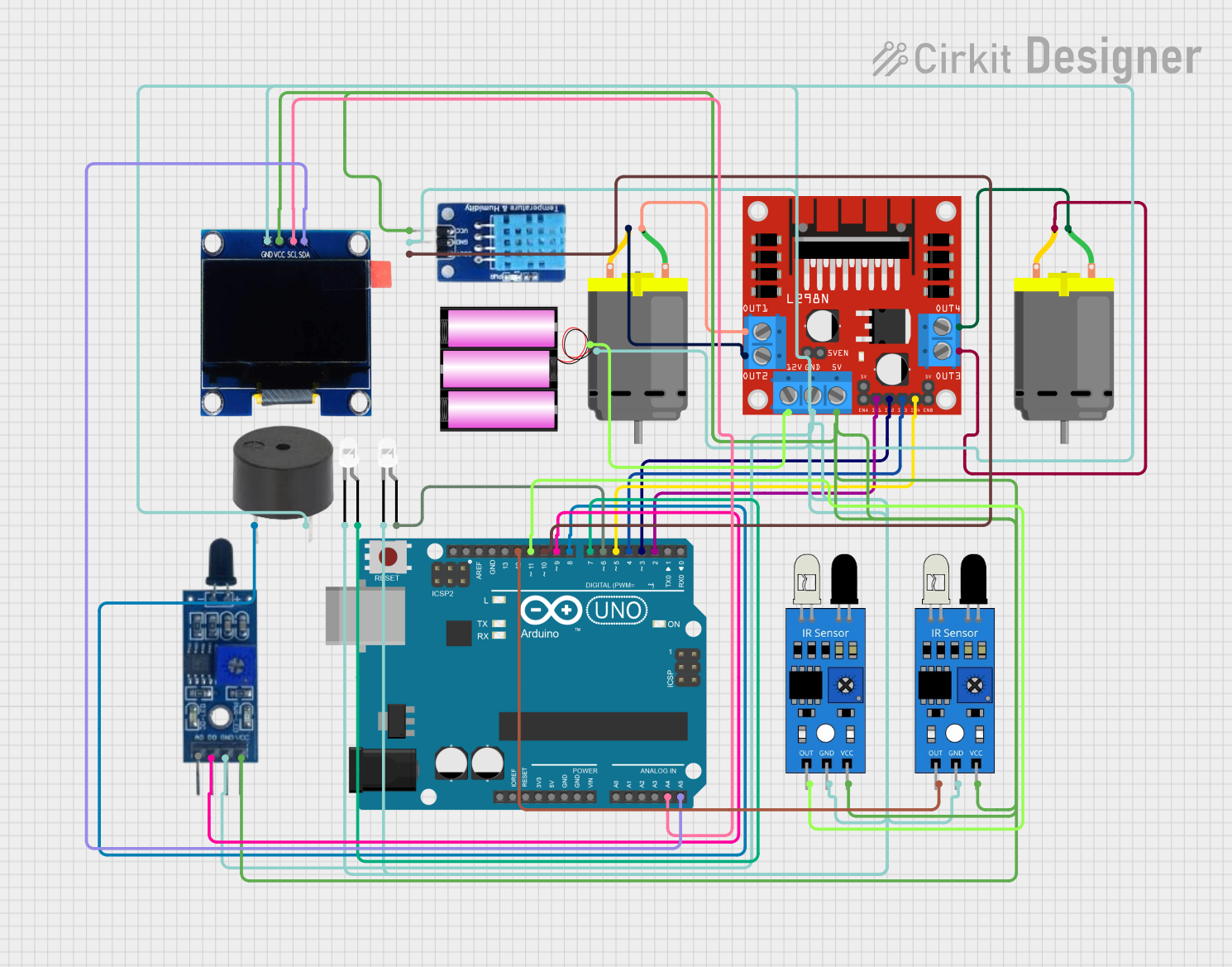
This circuit involves an Arduino UNO microcontroller interfacing with various sensors, actuators, and an OLED display. The components include a DHT11 temperature and humidity sensor, flame sensor, IR sensors, a buzzer, LEDs, a DC motor driver (L298N), DC motors, and a 1.3" OLED display. The circuit is designed to read sensor data, display it on the OLED screen, and control actuators based on sensor inputs.
Component List
Arduino UNO
- Description: Microcontroller board based on the ATmega328P.
- Pins: UNUSED, IOREF, Reset, 3.3V, 5V, GND, Vin, A0, A1, A2, A3, A4, A5, SCL, SDA, AREF, D13, D12, D11, D10, D9, D8, D7, D6, D5, D4, D3, D2, D1, D0
L298N DC Motor Driver
- Description: Dual H-Bridge motor driver.
- Pins: OUT1, OUT2, 12V, GND, 5V, OUT3, OUT4, 5V-ENA-JMP-I, 5V-ENA-JMP-O, +5V-J1, +5V-J2, ENA, IN1, IN2, IN3, IN4, ENB
DC Motor
- Description: Standard DC motor.
- Pins: pin 1, pin 2
Buzzer
- Description: Simple piezoelectric buzzer.
- Pins: PIN, GND
LED: Two Pin (white)
- Description: Standard white LED.
- Pins: cathode, anode
Flame Sensor
- Description: Sensor to detect flame or fire.
- Pins: VCC, GND, D0, A0
DHT11
- Description: Temperature and humidity sensor.
- Pins: DATA, GND, VCC
OLED 1.3"
- Description: 1.3-inch OLED display.
- Pins: GND, VCC, SCL, SDA
Battery 12V
- Description: 12V battery for power supply.
- Pins: +, -
IR Sensor
- Description: Infrared sensor for object detection.
- Pins: out, gnd, vcc
Wiring Details
Arduino UNO
- A4: Connected to SCL of OLED 1.3"
- A5: Connected to SDA of OLED 1.3"
- D12: Connected to out of IR Sensor
- D11: Connected to out of IR Sensor
- D10: Connected to DATA of DHT11
- D9: Connected to D0 of Flame Sensor
- D8: Connected to PIN of Buzzer
- D7: Connected to anode of LED: Two Pin (white)
- D6: Connected to anode of LED: Two Pin (white)
- D5: Connected to IN4 of L298N DC Motor Driver
- D4: Connected to IN3 of L298N DC Motor Driver
- D3: Connected to IN2 of L298N DC Motor Driver
- D2: Connected to IN1 of L298N DC Motor Driver
L298N DC Motor Driver
- OUT1: Connected to pin 1 of DC Motor
- OUT2: Connected to pin 2 of DC Motor
- OUT3: Connected to pin 2 of DC Motor
- OUT4: Connected to pin 1 of DC Motor
- 12V: Connected to + of Battery 12V
- GND: Connected to - of Battery 12V
- 5V: Connected to VCC of IR Sensor, DHT11, OLED 1.3", Flame Sensor
DC Motor
- pin 1: Connected to OUT1 of L298N DC Motor Driver
- pin 2: Connected to OUT2 of L298N DC Motor Driver
- pin 1: Connected to OUT4 of L298N DC Motor Driver
- pin 2: Connected to OUT3 of L298N DC Motor Driver
Buzzer
- PIN: Connected to D8 of Arduino UNO
- GND: Connected to - of Battery 12V
LED: Two Pin (white)
- anode: Connected to D7 of Arduino UNO
- cathode: Connected to - of Battery 12V
- anode: Connected to D6 of Arduino UNO
- cathode: Connected to - of Battery 12V
Flame Sensor
- D0: Connected to D9 of Arduino UNO
- GND: Connected to - of Battery 12V
- VCC: Connected to 5V of L298N DC Motor Driver
DHT11
- DATA: Connected to D10 of Arduino UNO
- GND: Connected to - of Battery 12V
- VCC: Connected to 5V of L298N DC Motor Driver
OLED 1.3"
- GND: Connected to - of Battery 12V
- VCC: Connected to 5V of L298N DC Motor Driver
- SCL: Connected to A4 of Arduino UNO
- SDA: Connected to A5 of Arduino UNO
Battery 12V
- +: Connected to 12V of L298N DC Motor Driver
- -: Connected to GND of L298N DC Motor Driver
IR Sensor
- out: Connected to D12 of Arduino UNO
- gnd: Connected to - of Battery 12V
- vcc: Connected to 5V of L298N DC Motor Driver
- out: Connected to D11 of Arduino UNO
- gnd: Connected to - of Battery 12V
- vcc: Connected to 5V of L298N DC Motor Driver
Code Documentation
#include <Wire.h>
#include <Adafruit_GFX.h>
#include <Adafruit_SSD1306.h>
#include <DHT.h>

// OLED display settings
#define SCREEN_WIDTH 128
#define SCREEN_HEIGHT 64
#define OLED_RESET -1
Adafruit_SSD1306 display(SCREEN_WIDTH, SCREEN_HEIGHT, &Wire, OLED_RESET);

// DHT11 settings
#define DHTPIN 10
#define DHTTYPE DHT11
DHT dht(DHTPIN, DHTTYPE);

// Flame sensor pin
#define FLAME_SENSOR_PIN 9

// Buzzer pin
#define BUZZER_PIN 8

// LED pins
#define LED1_PIN 7
#define LED2_PIN 6

// L298N motor driver pins
#define IN1_PIN 2
#define IN2_PIN 3
#define IN3_PIN 4
#define IN4_PIN 5

// IR sensor pins
#define IR_SENSOR1_PIN 11
#define IR_SENSOR2_PIN 12

void setup() {
  // Initialize serial communication
  Serial.begin(9600);

  // Initialize OLED display
  if (!display.begin(SSD1306_I2C_ADDRESS, OLED_RESET)) {
    Serial.println(F("SSD1306 allocation failed"));
    for (;;);
  }
  display.display();
  delay(2000);
  display.clearDisplay();

  // Initialize DHT11 sensor
  dht.begin();

  // Initialize flame sensor pin
  pinMode(FLAME_SENSOR_PIN, INPUT);

  // Initialize buzzer pin
  pinMode(BUZZER_PIN, OUTPUT);

  // Initialize LED pins
  pinMode(LED1_PIN, OUTPUT);
  pinMode(LED2_PIN, OUTPUT);

  // Initialize motor driver pins
  pinMode(IN1_PIN, OUTPUT);
  pinMode(IN2_PIN, OUTPUT);
  pinMode(IN3_PIN, OUTPUT);
  pinMode(IN4_PIN, OUTPUT);

  // Initialize IR sensor pins
  pinMode(IR_SENSOR1_PIN, INPUT);
  pinMode(IR_SENSOR2_PIN, INPUT);
}

void loop() {
  // Read DHT11 sensor data
  float humidity = dht.readHumidity();
  float temperature = dht.readTemperature();

  // Read flame sensor data