
Arduino UNO Controlled Stepper Motor with Force Sensing and Vibration Feedback
View and Edit Project In Cirkit Designer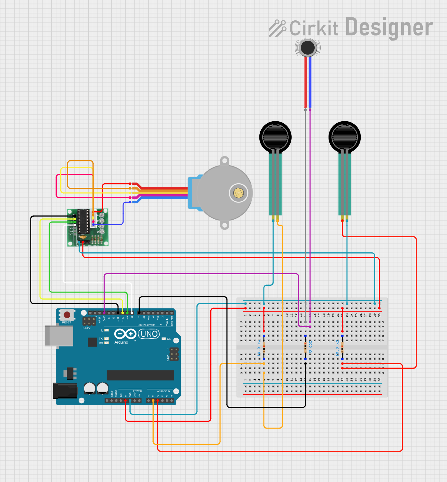
Circuit Documentation
Summary
This circuit involves an Arduino UNO microcontroller, a ULN 2003 driver, a gear-reduced stepper motor, resistors, force sensing resistors, and a vibration motor. The Arduino UNO controls the stepper motor through the ULN 2003 driver and reads inputs from the force sensing resistors. Additionally, the Arduino controls a vibration motor.
Component List
ULN 2003
- Description: A Darlington transistor array used to drive the stepper motor.
- Pins: IN1, IN2, IN3, IN4, IN5, IN6, IN7, GND, +, COIL1, COIL2, COIL3, COIL4, COIL5
Adafruit Gear-Reduced Stepper Motor (small)
- Description: A small stepper motor with gear reduction for increased torque.
- Pins: RED, ORANGE, YELLOW, PINK, BLUE
Arduino UNO
- Description: A microcontroller board based on the ATmega328P.
- Pins: UNUSED, IOREF, Reset, 3.3V, 5V, GND, Vin, A0, A1, A2, A3, A4, A5, SCL, SDA, AREF, D13, D12, D11, D10, D9, D8, D7, D6, D5, D4, D3, D2, D1, D0
Resistor (200 Ohms)
- Description: A resistor with a resistance of 200 Ohms.
- Pins: pin1, pin2
Resistor (10k Ohms)
- Description: A resistor with a resistance of 10k Ohms.
- Pins: pin1, pin2
Force Sensing Resistor
- Description: A resistor whose resistance changes with applied force.
- Pins: pin 0, pin 1
Vibration Motor
- Description: A small motor that provides vibration feedback.
- Pins: POS, NEG
Wiring Details
ULN 2003
- IN1: Connected to Arduino UNO D11
- IN2: Connected to Arduino UNO D10
- IN3: Connected to Arduino UNO D9
- IN4: Connected to Arduino UNO D8
- GND: Connected to Arduino UNO GND, Force Sensing Resistor pin 0, Force Sensing Resistor pin 1
- +: Connected to Arduino UNO 5V, Resistor (10k Ohms) pin2
- COIL1: Connected to Stepper Motor RED
- COIL2: Connected to Stepper Motor ORANGE
- COIL3: Connected to Stepper Motor YELLOW
- COIL4: Connected to Stepper Motor PINK
- COIL5: Connected to Stepper Motor BLUE
Adafruit Gear-Reduced Stepper Motor (small)
- RED: Connected to ULN 2003 COIL1
- ORANGE: Connected to ULN 2003 COIL2
- YELLOW: Connected to ULN 2003 COIL3
- PINK: Connected to ULN 2003 COIL4
- BLUE: Connected to ULN 2003 COIL5
Arduino UNO
- A1: Connected to Resistor (10k Ohms) pin1, Force Sensing Resistor pin 1
- A2: Connected to Resistor (10k Ohms) pin1, Force Sensing Resistor pin 0
- D7: Connected to Resistor (200 Ohms) pin2
- D11: Connected to ULN 2003 IN1
- D10: Connected to ULN 2003 IN2
- D9: Connected to ULN 2003 IN3
- D8: Connected to ULN 2003 IN4
- 5V: Connected to Resistor (10k Ohms) pin2, ULN 2003 +
- GND: Connected to Vibration Motor NEG, Force Sensing Resistor pin 0, Force Sensing Resistor pin 1, ULN 2003 GND
Resistor (200 Ohms)
- pin1: Connected to Vibration Motor POS
- pin2: Connected to Arduino UNO D7
Resistor (10k Ohms)
- pin1: Connected to Arduino UNO A1, Force Sensing Resistor pin 1
- pin2: Connected to Arduino UNO 5V, ULN 2003 +
Force Sensing Resistor
- pin 0: Connected to Arduino UNO GND, Force Sensing Resistor pin 1, ULN 2003 GND
- pin 1: Connected to Resistor (10k Ohms) pin1, Arduino UNO A1
Vibration Motor
- POS: Connected to Resistor (200 Ohms) pin1
- NEG: Connected to Arduino UNO GND
Code Documentation
Arduino UNO Code
void setup() {
  // put your setup code here, to run once:

}

void loop() {
  // put your main code here, to run repeatedly:

}
This code is a basic template for the Arduino UNO. The setup() function is where you initialize your components and settings, and the loop() function is where the main logic of your program runs repeatedly.