
Solar-Powered Smart Irrigation System with ESP32 and Soil Moisture Sensors
View and Edit Project In Cirkit Designer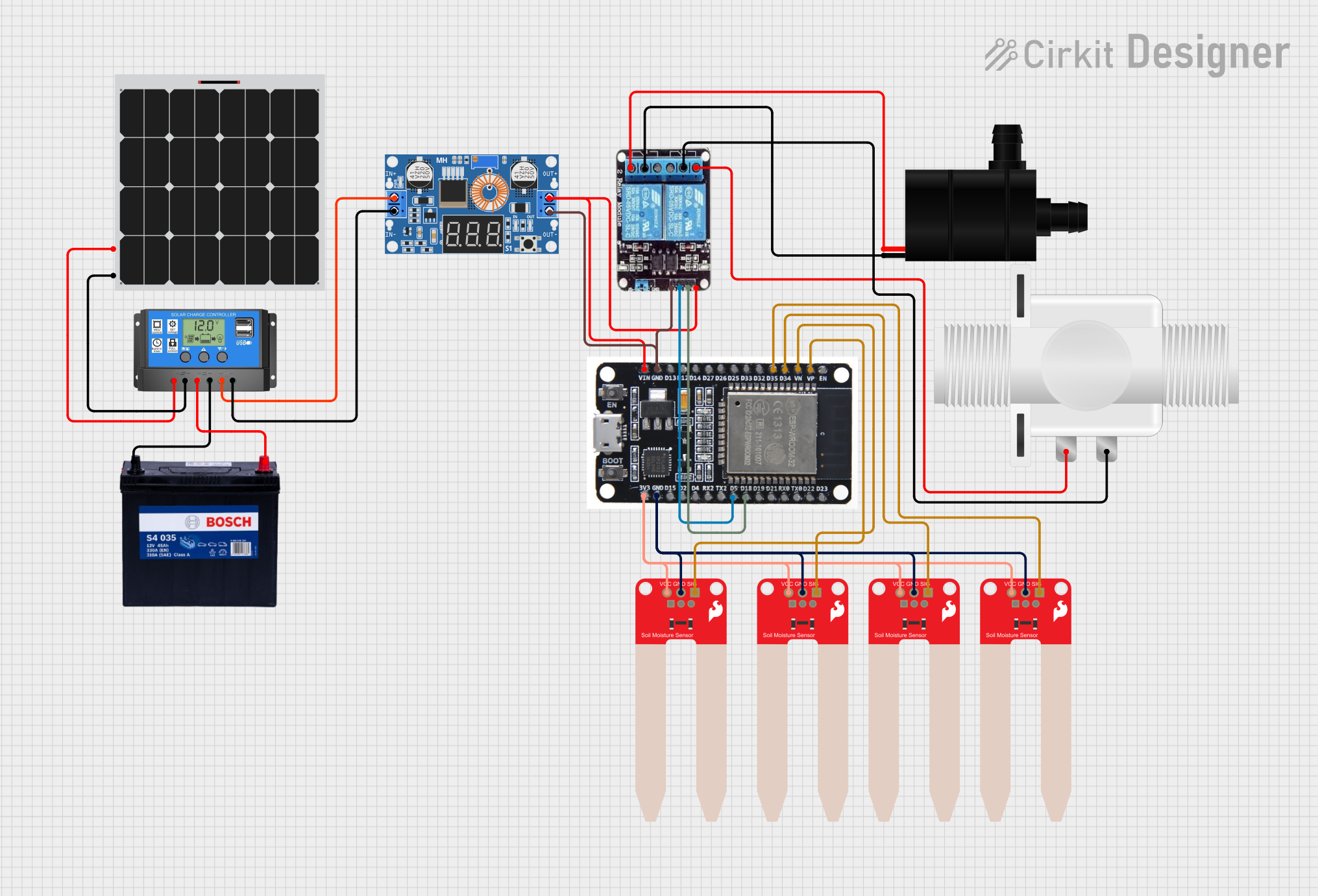
Circuit Documentation
Summary
This circuit is designed for an automated irrigation system powered by a solar panel. The system includes a solar charge controller, a 12V battery, a DC-DC buck converter, an ESP32 microcontroller, soil moisture sensors, a water pump, a solenoid valve, and a 2-channel relay module. The ESP32 reads soil moisture levels and controls the water pump and solenoid valve based on the moisture readings. The system is also integrated with Blynk for remote monitoring and control.
Component List
Solar Panel
- Description: Converts sunlight into electrical energy.
- Pins: +, -
Solar Charge Controller
- Description: Manages the power from the solar panel to charge the battery and power the load.
- Pins: Solar Cell +, Solar Cell -, Battery +, Battery -, Load +, Load -
12V 200Ah Battery
- Description: Stores electrical energy for use when the solar panel is not generating power.
- Pins: GND, 12V
SparkFun Soil Moisture Sensor
- Description: Measures the moisture level in the soil.
- Pins: VCC, GND, SIG
ESP32
- Description: Microcontroller used for reading sensor data and controlling actuators.
- Pins: EN, VP, VN, D34, D35, D32, D33, D25, D26, D27, D14, D12, D13, GND, VIN, 3V3, D15, D2, D4, RX2, TX2, D5, D18, D19, D21, RX0, TX0, D22, D23, BOOT
Water Pump
- Description: Pumps water to the irrigation system.
- Pins: VCC, GND
2ch Relay
- Description: Controls the water pump and solenoid valve.
- Pins: NC, COM, NO, VCC, IN2, IN1, GND
Plastic Solenoid Valve
- Description: Controls the flow of water in the irrigation system.
- Pins: pin1, pin2
XL4015 5A DC Buck Step-down
- Description: Steps down the voltage from the battery to a level suitable for the ESP32 and other components.
- Pins: Output +, Output -, Input +, Input -
Wiring Details
Solar Panel
- + connected to Solar Charge Controller (Solar Cell +)
- - connected to Solar Charge Controller (Solar Cell -)
Solar Charge Controller
- Solar Cell + connected to Solar Panel (+)
- Solar Cell - connected to Solar Panel (-)
- Battery + connected to 12V 200Ah Battery (12V)
- Battery - connected to 12V 200Ah Battery (GND)
- Load + connected to XL4015 5A DC Buck Step-down (Input +)
- Load - connected to XL4015 5A DC Buck Step-down (Input -)
12V 200Ah Battery
- 12V connected to Solar Charge Controller (Battery +)
- GND connected to Solar Charge Controller (Battery -)
SparkFun Soil Moisture Sensor (1)
- VCC connected to ESP32 (3V3)
- GND connected to ESP32 (GND)
- SIG connected to ESP32 (VP)
SparkFun Soil Moisture Sensor (2)
- VCC connected to ESP32 (3V3)
- GND connected to ESP32 (GND)
- SIG connected to ESP32 (VN)
SparkFun Soil Moisture Sensor (3)
- VCC connected to ESP32 (3V3)
- GND connected to ESP32 (GND)
- SIG connected to ESP32 (D34)
SparkFun Soil Moisture Sensor (4)
- VCC connected to ESP32 (3V3)
- GND connected to ESP32 (GND)
- SIG connected to ESP32 (D35)
ESP32
- 3V3 connected to SparkFun Soil Moisture Sensors (VCC)
- GND connected to SparkFun Soil Moisture Sensors (GND), XL4015 5A DC Buck Step-down (Output -), 2ch relay (GND)
- VIN connected to XL4015 5A DC Buck Step-down (Output +)
- VP connected to SparkFun Soil Moisture Sensor (1) (SIG)
- VN connected to SparkFun Soil Moisture Sensor (2) (SIG)
- D34 connected to SparkFun Soil Moisture Sensor (3) (SIG)
- D35 connected to SparkFun Soil Moisture Sensor (4) (SIG)
- D5 connected to 2ch relay (IN1)
- D18 connected to 2ch relay (IN2)
Water Pump
- VCC connected to 2ch relay (NC)
- GND connected to 2ch relay (COM)
2ch Relay
- NC connected to Water Pump (VCC)
- COM connected to Water Pump (GND), Plastic Solenoid Valve (pin2)
- NO connected to Plastic Solenoid Valve (pin1)
- VCC connected to XL4015 5A DC Buck Step-down (Output +)
- GND connected to XL4015 5A DC Buck Step-down (Output -)
- IN1 connected to ESP32 (D5)
- IN2 connected to ESP32 (D18)
Plastic Solenoid Valve
- pin1 connected to 2ch relay (NO)
- pin2 connected to 2ch relay (COM)
XL4015 5A DC Buck Step-down
- Input + connected to Solar Charge Controller (Load +)
- Input - connected to Solar Charge Controller (Load -)
- Output + connected to ESP32 (VIN), 2ch relay (VCC)
- Output - connected to ESP32 (GND), 2ch relay (GND)
Code Documentation
#define BLYNK_PRINT Serial
#include <WiFi.h>
#include <BlynkSimpleEsp32.h>

// Blynk Auth Token
char auth[] = "YourAuthToken";

// Your WiFi credentials
char ssid[] = "YourNetworkName";
char pass[] = "YourPassword";

// Pin definitions
#define SOIL_MOISTURE_PIN VP
#define WATER_PUMP_RELAY_PIN 5
#define SOLENOID_VALVE_RELAY_PIN 18

// Moisture threshold
int moistureThreshold = 500;

void setup() {
  // Debug console
  Serial.begin(115200);

  // Blynk setup
  Blynk.begin(auth, ssid, pass);

  // Initialize pins
  pinMode(SOIL_MOISTURE_PIN, INPUT);
  pinMode(WATER_PUMP_RELAY_PIN, OUTPUT);
  pinMode(SOLENOID_VALVE_RELAY_PIN, OUTPUT);
  digitalWrite(WATER_PUMP_RELAY_PIN, LOW);
  digitalWrite(SOLENOID_VALVE_RELAY_PIN, LOW);
}

void loop() {
  Blynk.run();

  // Read soil moisture
  int soilMoistureValue = analogRead(SOIL_MOISTURE_PIN);
  Serial.print("Soil Moisture: ");
  Serial.println(soilMoistureValue);

  // Send soil moisture value to Blynk
  Blynk.virtualWrite(V1, soilMoistureValue);

  // Control water pump and solenoid valve based on soil moisture
  if (soilMoistureValue < moistureThreshold) {
    digitalWrite(WATER_PUMP_RELAY_PIN, HIGH); // Turn on water pump
    digitalWrite(SOLENOID_VALVE_RELAY_PIN, HIGH); // Open solenoid valve
  } else {
    digitalWrite(WATER_PUMP_RELAY_PIN, LOW); // Turn off water pump
    digitalWrite(SOLENOID_VALVE_RELAY_PIN, LOW); // Close solenoid valve
  }

  delay(1000); // Wait for 1 second before next reading
}
This code initializes the ESP32, connects it to WiFi using Blynk, and reads soil moisture levels from the sensors. Based on the moisture readings, it controls the water pump and solenoid valve to maintain the desired soil moisture level. The soil moisture data is also sent to the Blynk app for remote monitoring.