Arduino UNO Based Environmental Monitoring Station with GSM Reporting
Circuit Documentation
Summary
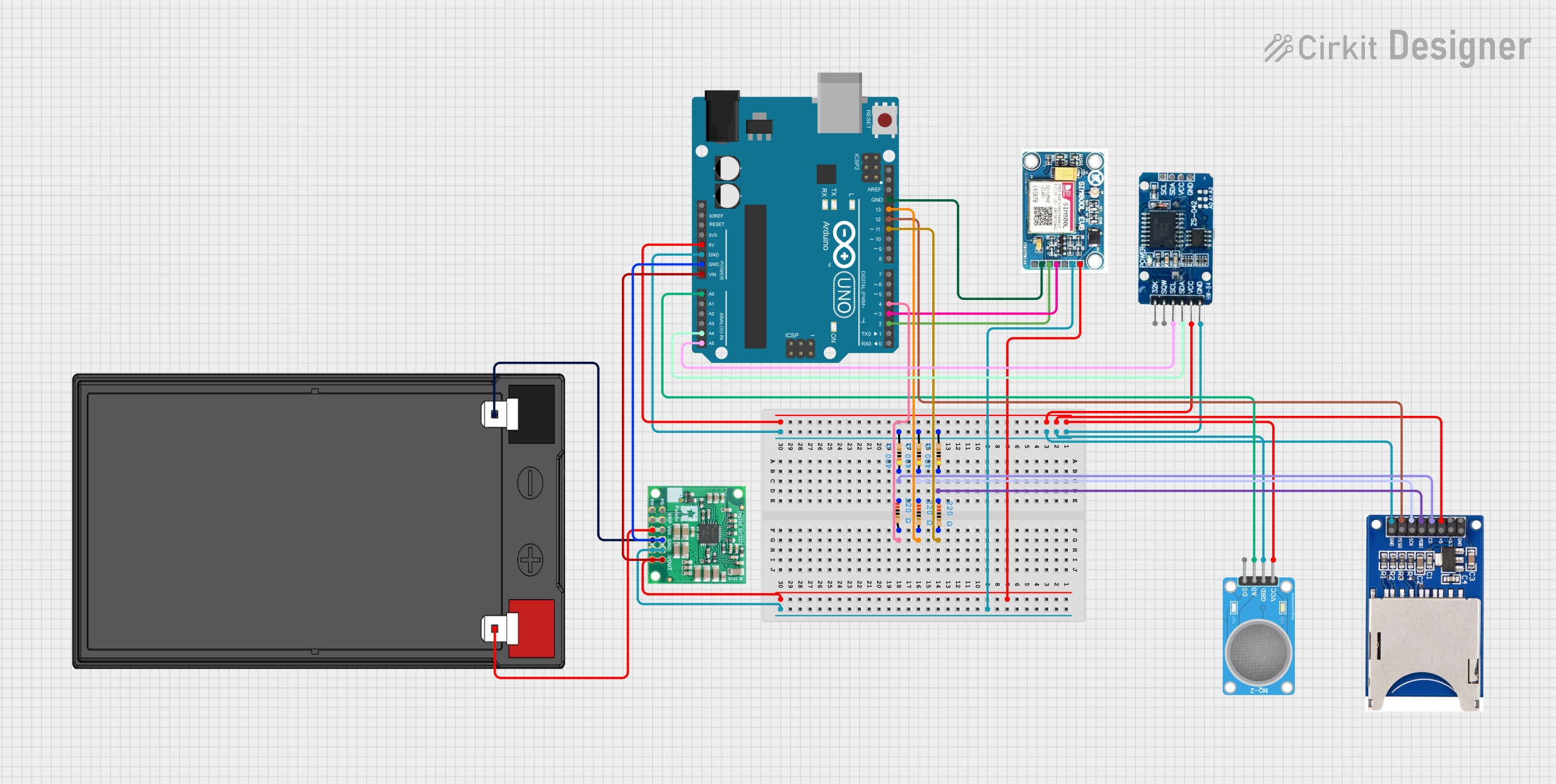
This document provides a detailed overview of a circuit that includes an Arduino UNO as the central microcontroller, interfaced with various peripherals including an MQ-2 gas sensor, a Real-Time Clock (RTC) DS3231, an SD card reader, a SIM 800L GSM module, and a 12V 7Ah battery with a 5V step-down voltage regulator. The circuit is designed to leverage the Arduino's capabilities to interact with these components, possibly for data logging, timekeeping, communication, and gas detection applications.
Component List
Arduino UNO
- Microcontroller board based on the ATmega328P
- It has 14 digital input/output pins, 6 analog inputs, a 16 MHz quartz crystal, a USB connection, a power jack, an ICSP header, and a reset button.
MQ-2 Gas Sensor
- A gas sensor used for detecting a variety of gases including LPG, smoke, and alcohol.
- It has both analog and digital output pins.
RTC DS3231
- A highly accurate I2C real-time clock with an integrated temperature-compensated crystal oscillator (TCXO) and crystal.
- It provides year, month, day, hour, minute, and second information.
SD Card Reader (2 Pins)
- A module for reading and writing data to an SD card.
- It interfaces with the microcontroller via SPI.
SIM 800L V2.0 GSM Module
- A GSM/GPRS module that can provide GSM functionalities to a microcontroller.
- It can perform tasks like sending SMS, making calls, and connecting to the internet over GPRS.
12V 7Ah Battery
- A lead-acid rechargeable battery providing a 12V power source.
5V, 5.5A Step-Down Voltage Regulator D36V50F5
- A voltage regulator that steps down the input voltage to a stable 5V output.
- It can supply up to 5.5A of current.
Resistors
- Multiple resistors with different resistance values used for various purposes in the circuit.
Wiring Details
Arduino UNO
5VandGNDare used to power the MQ-2 sensor, SD card reader, and RTC DS3231.Vinis connected to the 5V output of the step-down voltage regulator.GNDis also connected to the GND of the step-down voltage regulator and the SIM 800L GSM module.- Digital pins
D11,D13,D4,D3, andD2are used for interfacing with the SD card reader and the SIM 800L GSM module. - Analog pin
A0is connected to the MQ-2 sensor. - I2C pins
A4(SDA) andA5(SCL) are connected to the RTC DS3231.
MQ-2 Gas Sensor
VCCis connected to the 5V supply from the Arduino.GNDis connected to the common ground.A0is connected to the analog inputA0on the Arduino.
RTC DS3231
VCCis connected to the 5V supply from the Arduino.GNDis connected to the common ground.SDAandSCLare connected toA4andA5on the Arduino, respectively.
SD Card Reader (2 Pins)
5VandGNDare connected to the 5V supply and common ground, respectively.MOSI,SCK,CS, andMISOare connected to digital pinsD11,D13,D4, andD12on the Arduino, respectively.
SIM 800L V2.0 GSM Module
5V/4Vis connected to the 5V output of the step-down voltage regulator.GNDis connected to the common ground.SIM_TXDandSIM.RXDare connected to digital pinsD3andD2on the Arduino, respectively.
12V 7Ah Battery
12v +is connected to theVINof the step-down voltage regulator.12v -is connected to theGNDof the step-down voltage regulator.
5V, 5.5A Step-Down Voltage Regulator D36V50F5
VINis connected to the12v +of the battery.GNDis connected to the12v -of the battery and the common ground.VOUTprovides 5V which is used to power the ArduinoVinand the SIM 800L GSM module.
Resistors
- Several resistors are used in the circuit, likely for pull-up/pull-down or current limiting purposes. They are connected to various components and the Arduino.
Documented Code
Arduino UNO Code (sketch.ino)
void setup() {
  // put your setup code here, to run once:

}

void loop() {
  // put your main code here, to run repeatedly:

}
This code is a template and does not contain any specific functionality. It provides the basic structure for an Arduino sketch with setup() and loop() functions where the user can add initialization code and the main code to be executed repeatedly, respectively.