
Circuit Documentation
Summary
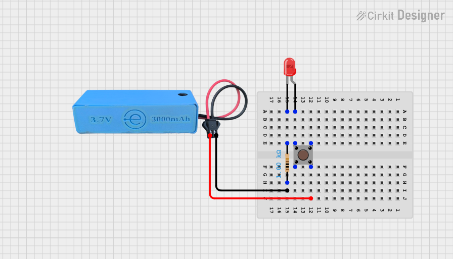
This circuit consists of a pushbutton, a resistor, an LED, and a power source. The pushbutton controls the LED, allowing it to light up when pressed. The resistor is used to limit the current flowing through the LED to prevent damage. The power source provides the necessary voltage for the circuit to operate.
Component List
LED: Two Pin (red)
- Pins: cathode, anode
- Description: A red LED used to indicate the status of the circuit.
- Purpose: To emit light when the circuit is completed.
Pushbutton
- Pins: Pin 3 (out), Pin 4 (out), Pin 1 (in), Pin 2 (in)
- Description: A pushbutton switch used to control the flow of current in the circuit.
- Purpose: To allow the user to control the LED by pressing the button.
Resistor
- Pins: pin1, pin2
- Description: A resistor with a resistance of 1000 Ohms.
- Purpose: To limit the current flowing through the LED to prevent damage.
MAHIR 1.mini
- Pins: GND, 3.7v
- Description: A power source providing 3.7 volts.
- Purpose: To supply the necessary voltage for the circuit to operate.
Wiring Details
LED: Two Pin (red)
- Cathode: Connected to pin2 of the Resistor.
- Anode: Connected to Pin 1 (in) of the Pushbutton.
Pushbutton
- Pin 4 (out): Connected to 3.7v of the MAHIR 1.mini.
- Pin 1 (in): Connected to the anode of the LED.
Resistor
- Pin1: Connected to GND of the MAHIR 1.mini.
- Pin2: Connected to the cathode of the LED.
MAHIR 1.mini
- GND: Connected to pin1 of the Resistor.
- 3.7v: Connected to Pin 4 (out) of the Pushbutton.
Code
There is no microcontroller code associated with this circuit.
This documentation provides a comprehensive overview of the circuit, including a summary, detailed component descriptions, and wiring details. The circuit is designed to light up an LED when the pushbutton is pressed, with a resistor in place to limit the current and a power source to provide the necessary voltage.