
Stepper Motor Control System with TB6600 Driver and Relay Integration
View and Edit Project In Cirkit Designer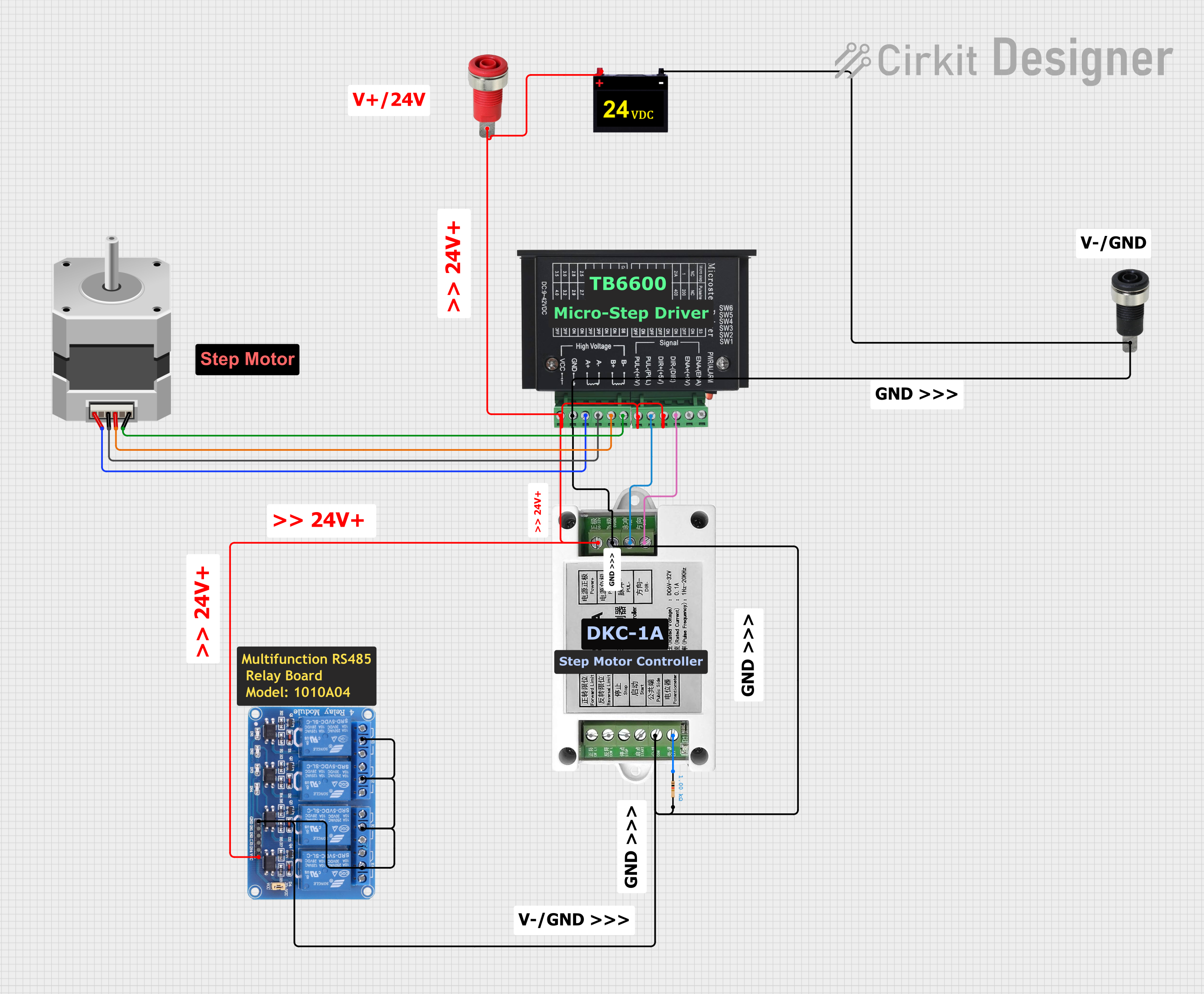
Circuit Documentation
Summary
This document provides a detailed overview of a circuit designed to control a stepper motor using a TB6600 micro-stepping motor driver and a DKC-1A stepper motor controller. The circuit also includes a relay module for additional control and a power supply for the necessary voltage levels. The connections between the components are described in detail, and the document is structured to provide a clear understanding of the circuit's functionality.
Component List
Red Panel Mount 4mm Banana Socket
- Pins: Red_Pin
- Description: A red banana socket for power connections.
- Purpose: Provides a connection point for the positive power supply.
Stepper Motor (Bipolar)
- Pins: D, B, C, A
- Description: A bipolar stepper motor.
- Purpose: Converts electrical pulses into mechanical movement.
TB6600 Micro Stepping Motor Driver
- Pins: ENA-, ENA+, DIR-, DIR+, PUL-, PUL+, B-, B+, A-, A+, GND, VCC
- Description: A micro-stepping driver for controlling the stepper motor.
- Purpose: Drives the stepper motor with precise control over its movement.
Black Panel Mount 4mm Banana Socket
- Pins: Black_Pin
- Description: A black banana socket for ground connections.
- Purpose: Provides a connection point for the ground.
DKC-1A Stepper Motor Controller
- Pins: Reversal Limit, Stop, Start, COM/Ground, Forward Limit, Potentiometer, Power+, Power-, PUL-, DIR-
- Description: A controller for the stepper motor.
- Purpose: Provides control signals to the stepper motor driver.
Resistor
- Pins: pin1, pin2
- Description: A resistor with a resistance of 1000 Ohms.
- Purpose: Used for current limiting or voltage division.
Relay 4 Channel 5v
- Pins: GND, IN1, IN2, IN3, IN4, VCC, COM1, COM2, COM3, COM4, NO1, NO2, NO3, NO4, NC1, NC2, NC3, NC4
- Description: A 4-channel relay module.
- Purpose: Provides switching capabilities for controlling other devices.
24VDC Power Supply
- Pins: +24VDC, 0V
- Description: A 24V DC power supply.
- Purpose: Provides the necessary voltage for the circuit.
Wiring Details
Red Panel Mount 4mm Banana Socket
- Red_Pin is connected to:
- +24VDC of the 24VDC Power Supply
- VCC of the Relay 4 Channel 5v
- Power+ of the DKC-1A Stepper Motor Controller
- VCC of the TB6600 Micro Stepping Motor Driver
- DIR+ of the TB6600 Micro Stepping Motor Driver
- PUL+ of the TB6600 Micro Stepping Motor Driver
Stepper Motor (Bipolar)
- D is connected to B- of the TB6600 Micro Stepping Motor Driver
- B is connected to B+ of the TB6600 Micro Stepping Motor Driver
- C is connected to A- of the TB6600 Micro Stepping Motor Driver
- A is connected to A+ of the TB6600 Micro Stepping Motor Driver
TB6600 Micro Stepping Motor Driver
- DIR- is connected to DIR- of the DKC-1A Stepper Motor Controller
- PUL- is connected to PUL- of the DKC-1A Stepper Motor Controller
- B- is connected to D of the Stepper Motor (Bipolar)
- B+ is connected to B of the Stepper Motor (Bipolar)
- A- is connected to C of the Stepper Motor (Bipolar)
- A+ is connected to A of the Stepper Motor (Bipolar)
- GND is connected to:
- 0V of the 24VDC Power Supply
- Black_Pin of the Black Panel Mount 4mm Banana Socket
- GND of the Relay 4 Channel 5v
- COM1 of the Relay 4 Channel 5v
- COM2 of the Relay 4 Channel 5v
- COM3 of the Relay 4 Channel 5v
- COM4 of the Relay 4 Channel 5v
- COM/Ground of the DKC-1A Stepper Motor Controller
- Power- of the DKC-1A Stepper Motor Controller
- pin2 of the Resistor
Black Panel Mount 4mm Banana Socket
- Black_Pin is connected to:
- 0V of the 24VDC Power Supply
- GND of the Relay 4 Channel 5v
- COM1 of the Relay 4 Channel 5v
- COM2 of the Relay 4 Channel 5v
- COM3 of the Relay 4 Channel 5v
- COM4 of the Relay 4 Channel 5v
- COM/Ground of the DKC-1A Stepper Motor Controller
- Power- of the DKC-1A Stepper Motor Controller
- pin2 of the Resistor
DKC-1A Stepper Motor Controller
- DIR- is connected to DIR- of the TB6600 Micro Stepping Motor Driver
- PUL- is connected to PUL- of the TB6600 Micro Stepping Motor Driver
- Power+ is connected to +24VDC of the 24VDC Power Supply
- Power- is connected to 0V of the 24VDC Power Supply
- COM/Ground is connected to 0V of the 24VDC Power Supply
- Potentiometer is connected to pin1 of the Resistor
Resistor
- pin1 is connected to Potentiometer of the DKC-1A Stepper Motor Controller
- pin2 is connected to 0V of the 24VDC Power Supply
Relay 4 Channel 5v
- VCC is connected to +24VDC of the 24VDC Power Supply
- GND is connected to 0V of the 24VDC Power Supply
- COM1 is connected to 0V of the 24VDC Power Supply
- COM2 is connected to 0V of the 24VDC Power Supply
- COM3 is connected to 0V of the 24VDC Power Supply
- COM4 is connected to 0V of the 24VDC Power Supply
24VDC Power Supply
- +24VDC is connected to:
- Red_Pin of the Red Panel Mount 4mm Banana Socket
- VCC of the Relay 4 Channel 5v
- Power+ of the DKC-1A Stepper Motor Controller
- VCC of the TB6600 Micro Stepping Motor Driver
- DIR+ of the TB6600 Micro Stepping Motor Driver
- PUL+ of the TB6600 Micro Stepping Motor Driver
- 0V is connected to:
- Black_Pin of the Black Panel Mount 4mm Banana Socket
- GND of the Relay 4 Channel 5v
- COM1 of the Relay 4 Channel 5v
- COM2 of the Relay 4 Channel 5v
- COM3 of the Relay 4 Channel 5v
- COM4 of the Relay 4 Channel 5v
- COM/Ground of the DKC-1A Stepper Motor Controller
- Power- of the DKC-1A Stepper Motor Controller
- pin2 of the Resistor
- GND of the TB6600 Micro Stepping Motor Driver
Code
There is no code provided for this circuit.