Cirkit Designer
Your all-in-one circuit design IDE
Home /
Project Documentation
Arduino-Controlled APA102 LED Strip with Battery Power and Rocker Switch

Circuit Documentation
Summary
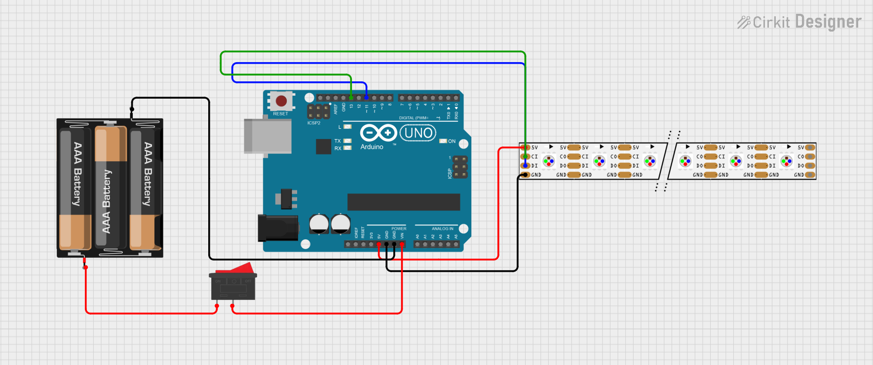
This circuit integrates an Arduino UNO microcontroller with an APA102 LED Strip and is powered by a 3xAA battery pack. A rocker switch is included to control the power supply to the Arduino UNO. The Arduino UNO controls the LED strip by sending data through its digital pins.
Component List
Arduino UNO
- Description: A microcontroller board based on the ATmega328P.
- Purpose: Acts as the central controller for the circuit, interfacing with the LED strip and managing power from the battery pack.
- Pins: UNUSED, IOREF, Reset, 3.3V, 5V, GND, Vin, A0-A5, SCL, SDA, AREF, D13-D0.
APA102 LED Strip
- Description: A strip of individually addressable RGB LEDs.
- Purpose: Displays various colors and patterns as instructed by the Arduino UNO.
- Pins: GND, DI, CI, +5V, DO, CO.
3xAA Battery
- Description: A battery pack holding three AA batteries.
- Purpose: Provides power to the Arduino UNO and the LED strip.
- Pins: VCC, GND.
Rocker Switch
- Description: A simple on/off switch.
- Purpose: Allows the user to control the power supply to the Arduino UNO.
- Pins: 1, 2.
Wiring Details
Arduino UNO
- 5V connected to APA102 LED Strip +5V
- GND connected to APA102 LED Strip GND and 3xAA Battery GND
- Vin connected to Rocker Switch pin 2
- D13 connected to APA102 LED Strip CI (Clock Input)
- D11 connected to APA102 LED Strip DI (Data Input)
APA102 LED Strip
- GND connected to Arduino UNO GND
- DI connected to Arduino UNO D11
- CI connected to Arduino UNO D13
- +5V connected to Arduino UNO 5V
3xAA Battery
- VCC connected to Rocker Switch pin 1
- GND connected to Arduino UNO GND
Rocker Switch
- Pin 1 connected to 3xAA Battery VCC
- Pin 2 connected to Arduino UNO Vin
Documented Code
Arduino UNO Code (sketch.ino)
void setup() {
  // put your setup code here, to run once:

}

void loop() {
  // put your main code here, to run repeatedly:

}
Note: The provided code is a template and does not include specific instructions for controlling the APA102 LED Strip. The user should add the necessary code to initialize the LED strip and to send data for controlling the light patterns.