
Arduino Mega ADK Airline Seat Booking System with LED Indicators
View and Edit Project In Cirkit Designer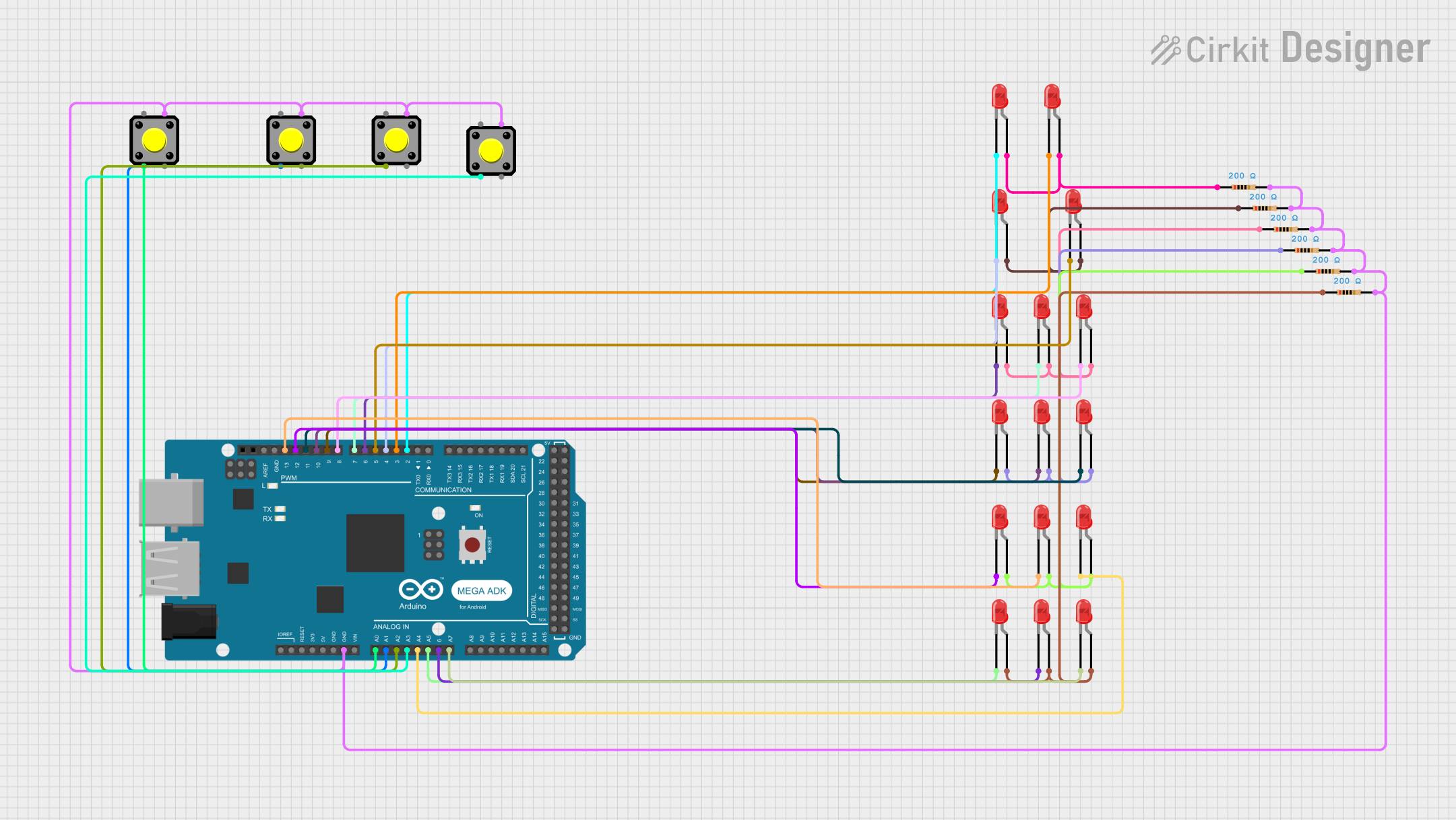
Circuit Documentation
Summary
This circuit is an Airline Seat Booking System using an Arduino Mega ADK (Rev3) microcontroller. It includes 16 red LEDs to represent seats and 4 pushbuttons for user input. The system allows users to book seats in either First Class or Second Class, with the status of each seat indicated by the corresponding LED.
Component List
LED: Two Pin (red)
- Description: Red LED with two pins (anode and cathode).
- Purpose: Indicates the status of seats (available or occupied).
Arduino Mega ADK (Rev3)
- Description: A microcontroller board based on the ATmega2560.
- Purpose: Controls the LEDs and reads input from the pushbuttons.
Resistor
- Description: 200 Ohms resistor.
- Purpose: Limits the current to the LEDs to prevent damage.
Pushbutton
- Description: A simple pushbutton with four pins.
- Purpose: Allows user input for selecting class, row, and seat.
Wiring Details
LED: Two Pin (red)
LED 1
- Cathode: Connected to Arduino Mega ADK (Rev3) pin D2 PWM
- Anode: Connected to the anode of LED 2 and Resistor 1 pin1
LED 2
- Cathode: Connected to Arduino Mega ADK (Rev3) pin D3 PWM
- Anode: Connected to the anode of LED 1 and Resistor 1 pin1
LED 3
- Cathode: Connected to Arduino Mega ADK (Rev3) pin D4 PWM
- Anode: Connected to the anode of LED 4 and LED 5 and Resistor 2 pin1
LED 4
- Cathode: Connected to Arduino Mega ADK (Rev3) pin D5 PWM
- Anode: Connected to the anode of LED 3 and LED 5 and Resistor 2 pin1
LED 5
- Cathode: Connected to Arduino Mega ADK (Rev3) pin D6 PWM
- Anode: Connected to the anode of LED 3 and LED 4 and Resistor 2 pin1
LED 6
- Cathode: Connected to Arduino Mega ADK (Rev3) pin D7 PWM
- Anode: Connected to the anode of LED 7 and LED 8 and Resistor 3 pin1
LED 7
- Cathode: Connected to Arduino Mega ADK (Rev3) pin D8 PWM
- Anode: Connected to the anode of LED 6 and LED 8 and Resistor 3 pin1
LED 8
- Cathode: Connected to Arduino Mega ADK (Rev3) pin D9 PWM
- Anode: Connected to the anode of LED 6 and LED 7 and Resistor 3 pin1
LED 9
- Cathode: Connected to Arduino Mega ADK (Rev3) pin D10 PWM
- Anode: Connected to the anode of LED 10 and LED 11 and Resistor 4 pin1
LED 10
- Cathode: Connected to Arduino Mega ADK (Rev3) pin D11 PWM
- Anode: Connected to the anode of LED 9 and LED 11 and Resistor 4 pin1
LED 11
- Cathode: Connected to Arduino Mega ADK (Rev3) pin D12 PWM
- Anode: Connected to the anode of LED 9 and LED 10 and Resistor 4 pin1
LED 12
- Cathode: Connected to Arduino Mega ADK (Rev3) pin D13 PWM
- Anode: Connected to the anode of LED 13 and LED 14 and Resistor 5 pin1
LED 13
- Cathode: Connected to Arduino Mega ADK (Rev3) pin A4
- Anode: Connected to the anode of LED 12 and LED 14 and Resistor 5 pin1
LED 14
- Cathode: Connected to Arduino Mega ADK (Rev3) pin A5
- Anode: Connected to the anode of LED 12 and LED 13 and Resistor 5 pin1
LED 15
- Cathode: Connected to Arduino Mega ADK (Rev3) pin A6
- Anode: Connected to the anode of LED 16 and Resistor 6 pin1
LED 16
- Cathode: Connected to Arduino Mega ADK (Rev3) pin A7
- Anode: Connected to the anode of LED 15 and Resistor 6 pin1
Arduino Mega ADK (Rev3)
- D2 PWM: Connected to the cathode of LED 1
- D3 PWM: Connected to the cathode of LED 2
- D4 PWM: Connected to the cathode of LED 3
- D5 PWM: Connected to the cathode of LED 4
- D6 PWM: Connected to the cathode of LED 5
- D7 PWM: Connected to the cathode of LED 6
- D8 PWM: Connected to the cathode of LED 7
- D9 PWM: Connected to the cathode of LED 8
- D10 PWM: Connected to the cathode of LED 9
- D11 PWM: Connected to the cathode of LED 10
- D12 PWM: Connected to the cathode of LED 11
- D13 PWM: Connected to the cathode of LED 12
- A4: Connected to the cathode of LED 13
- A5: Connected to the cathode of LED 14
- A6: Connected to the cathode of LED 15
- A7: Connected to the cathode of LED 16
- A0: Connected to Pin 2 of Pushbutton 1
- A1: Connected to Pin 2 of Pushbutton 2
- A2: Connected to Pin 2 of Pushbutton 3
- A3: Connected to Pin 2 of Pushbutton 4
- GND: Connected to Pin 4 of all Pushbuttons
Resistor
Resistor 1
- Pin 1: Connected to the anode of LED 1 and LED 2
- Pin 2: Connected to GND
Resistor 2
- Pin 1: Connected to the anode of LED 3, LED 4, and LED 5
- Pin 2: Connected to GND
Resistor 3
- Pin 1: Connected to the anode of LED 6, LED 7, and LED 8
- Pin 2: Connected to GND
Resistor 4
- Pin 1: Connected to the anode of LED 9, LED 10, and LED 11
- Pin 2: Connected to GND
Resistor 5
- Pin 1: Connected to the anode of LED 12, LED 13, and LED 14
- Pin 2: Connected to GND
Resistor 6
- Pin 1: Connected to the anode of LED 15 and LED 16
- Pin 2: Connected to GND
Pushbutton
Pushbutton 1
- Pin 2: Connected to Arduino Mega ADK (Rev3) pin A0
- Pin 4: Connected to GND
Pushbutton 2
- Pin 2: Connected to Arduino Mega ADK (Rev3) pin A1
- Pin 4: Connected to GND
Pushbutton 3
- Pin 2: Connected to Arduino Mega ADK (Rev3) pin A2
- Pin 4: Connected to GND
Pushbutton 4
- Pin 2: Connected to Arduino Mega ADK (Rev3) pin A3
- Pin 4: Connected to GND
Code Documentation
// Airline Seat Booking System with Four Buttons
const int totalSeats = 16;         // Total seats: 4 First Class + 12 Second Class
bool seats[totalSeats] = {false}; // Seat occupancy (false = available, true = occupied)

// LED pin assignments
const int ledPins[totalSeats] = {
  2, 3, 4, 5,   // First Class seats (1+1 configuration)
  6, 7, 8,      // Second Class Row 1
  9, 10, 11,    // Second Class Row 2
  12, 13, A4,   // Second Class Row 3
  A5, A6, A7    // Second Class Row 4
};

// Button pin assignments
const int buttonB1 = A