
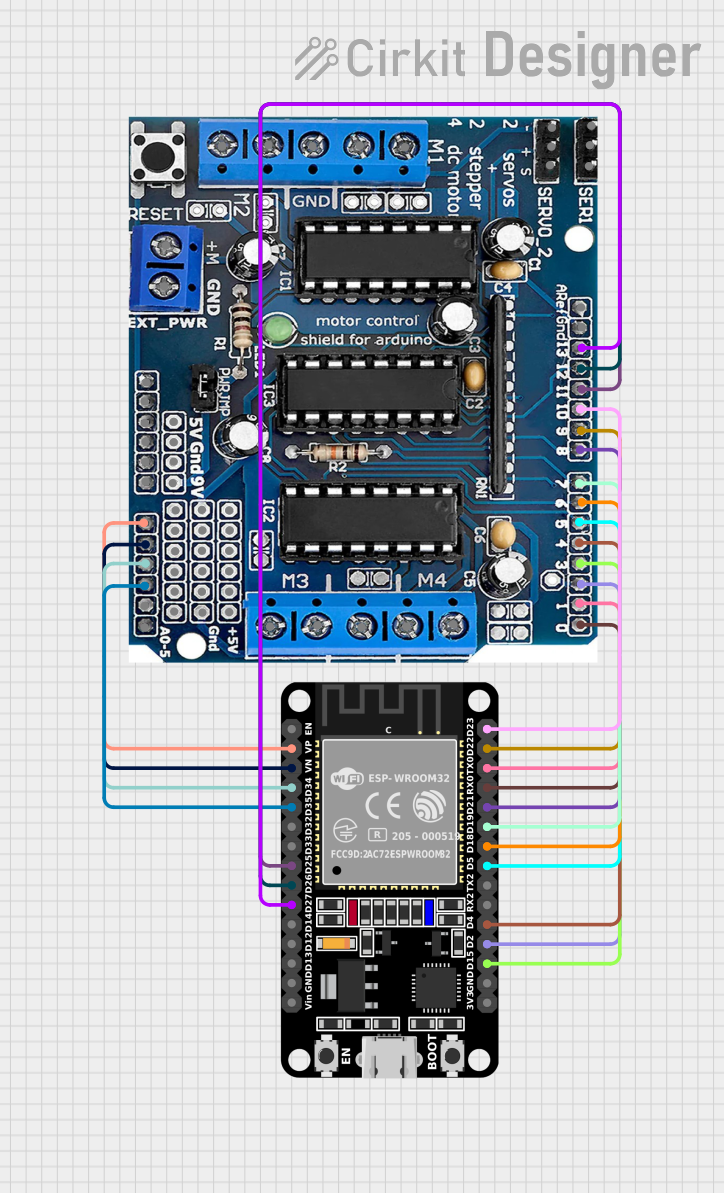
Circuit Documentation
Summary of the Circuit
This circuit is designed to interface an ESP32 microcontroller with an L293D motor driver shield. The primary function of this circuit is to control motors and potentially other actuators like servos, using the ESP32's GPIO pins to send commands to the L293D, which in turn drives the motors. The ESP32 also reads analog inputs through its ADC-capable pins connected to the L293D's analog pins. Serial communication between the ESP32 and L293D is established for data transfer.
Component List
ESP32 (30 pin)
- Description: A powerful microcontroller with Wi-Fi and Bluetooth capabilities, suitable for a wide range of applications, from simple to advanced IoT applications.
- Pins: EN, VP, VN, D34, D35, D32, D33, D25, D26, D27, D14, D12, D13, GND, Vin, D23, D22, TX0, RX0, D21, D19, D18, D5, TX2, RX2, D4, D2, D15, 3V3
L293D Motor Driver Shield
- Description: A motor driver shield that can drive up to 4 DC motors or 2 stepper motors, 2 servos, and has several GPIOs for interfacing with sensors and other peripherals.
- Pins: 5V, GND, +, Servo1, Servo2, RX/DO, TX/D1, 9V, A0, A1, A2, A3, A4/SDA, A5/SCL, VIN, 3.3V, RESET, D2, D3, D4, D5, D6, D7, D8, D9, D10, D11, D12, D13
Wiring Details
ESP32 (30 pin)
- VP connected to L293D A0
- VN connected to L293D A1
- D34 connected to L293D A2
- D35 connected to L293D A3
- D25 connected to L293D D11
- D26 connected to L293D D12
- D27 connected to L293D D13
- D23 connected to L293D D10
- D22 connected to L293D D9
- TX0 connected to L293D TX/D1
- RX0 connected to L293D RX/DO
- D21 connected to L293D D8
- D19 connected to L293D D7
- D18 connected to L293D D6
- D5 connected to L293D D5
- D4 connected to L293D D4
- D2 connected to L293D D2
- D15 connected to L293D D3
L293D Motor Driver Shield
- A0 connected to ESP32 VP
- A1 connected to ESP32 VN
- A2 connected to ESP32 D34
- A3 connected to ESP32 D35
- D11 connected to ESP32 D25
- D12 connected to ESP32 D26
- D13 connected to ESP32 D27
- D10 connected to ESP32 D23
- D9 connected to ESP32 D22
- TX/D1 connected to ESP32 TX0
- RX/DO connected to ESP32 RX0
- D8 connected to ESP32 D21
- D7 connected to ESP32 D19
- D6 connected to ESP32 D18
- D5 connected to ESP32 D5
- D4 connected to ESP32 D4
- D2 connected to ESP32 D2
- D3 connected to ESP32 D15
Documented Code
// This code interfaces the L293D motor driver shield with the ESP32 Dev Kit V1.
// It sets up the necessary pin mappings and initializes the pins for motor control.
// Additionally, it configures the analog pins and power connections.

#include <Servo.h>
Servo myServo; // Create a servo object

void setup() {
  // Initialize serial communication
  Serial.begin(115200);
  // Define pin modes for motor control
  pinMode(2, OUTPUT);  // L293D D2 -> ESP32 D2
  pinMode(15, OUTPUT); // L293D D3 -> ESP32 D15
  pinMode(4, OUTPUT);  // L293D D4 -> ESP32 D4
  pinMode(5, OUTPUT);  // L293D D5 -> ESP32 D5
  pinMode(18, OUTPUT); // L293D D6 -> ESP32 D18
  pinMode(19, OUTPUT); // L293D D7 -> ESP32 D19
  pinMode(21, OUTPUT); // L293D D8 -> ESP32 D21
  pinMode(22, OUTPUT); // L293D D9 -> ESP32 D22
  pinMode(23, OUTPUT); // L293D D10 -> ESP32 D23
  pinMode(25, OUTPUT); // L293D D11 -> ESP32 D25
  pinMode(26, OUTPUT); // L293D D12 -> ESP32 D26
  pinMode(27, OUTPUT); // L293D D13 -> ESP32 D27
  // Define pin modes for analog inputs
  pinMode(36, INPUT);  // L293D A0 -> ESP32 VP
  pinMode(39, INPUT);  // L293D A1 -> ESP32 VN
  pinMode(34, INPUT);  // L293D A2 -> ESP32 D34
  pinMode(35, INPUT);  // L293D A3 -> ESP32 D35
  // Define pin modes for serial communication
  pinMode(1, OUTPUT);  // L293D TX/D1 -> ESP32 TX0
  pinMode(3, INPUT);   // L293D RX/DO -> ESP32 RX0
  // Power connections (handled by hardware)
  // L293D 5V -> ESP32 3V3
  // L293D GND -> ESP32 GND
  // L293D VIN -> ESP32 Vin
  // Attach the servo to pin D2
  myServo.attach(2); // L293D D2 -> ESP32 D2
}

void loop() {
  // Example servo control logic
  myServo.write(0);   // Move servo to 0 degrees
  delay(1000);        // Wait for 1 second
  myServo.write(90);  // Move servo to 90 degrees
  delay(1000);        // Wait for 1 second
  myServo.write(180); // Move servo to 180 degrees
  delay(1000);        // Wait for 1 second
}
This code is designed to run on the ESP32 microcontroller and controls a servo motor through the L293D motor driver shield. It sets up the necessary GPIO pins as outputs for motor control and inputs for analog readings. The servo is attached to pin D2 of the ESP32, and the code includes an example of how to move the servo to different positions.