
Circuit Documentation
Summary of the Circuit
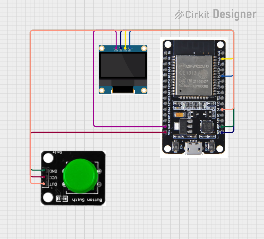
This circuit integrates an ESP32 microcontroller with a 0.96" OLED display and a green button. The ESP32 serves as the central processing unit, controlling the OLED display and reading input from the button. The OLED display is used for visual output, while the green button serves as a user input device. The circuit is designed to operate with a common ground and power supply connections, with the ESP32 providing control signals to the OLED and reading the button state.
Component List
ESP32
- Description: A microcontroller with Wi-Fi and Bluetooth capabilities, featuring a wide range of GPIO pins for interfacing with various peripherals.
- Pins: EN, VP, VN, D34, D35, D32, D33, D25, D26, D27, D14, D12, D13, GND, VIN, 3V3, D15, D2, D4, RX2, TX2, D5, D18, D19, D21, RX0, TX0, D22, D23, BOOT
0.96" OLED
- Description: A small display module for visual output, interfacing via I2C communication protocol.
- Pins: GND, VDD, SCK, SDA
Green Button
- Description: A simple push-button switch used for user input.
- Pins: OUT, VCC, GND
Wiring Details
ESP32
- GND: Connected to the OLED GND and Green Button GND.
- VIN: Connected to the Green Button VCC.
- 3V3: Connected to the OLED VDD.
- D4: Connected to the Green Button OUT.
- D21 (SDA): Connected to the OLED SDA.
- D22 (SCK): Connected to the OLED SCK.
0.96" OLED
- GND: Connected to the ESP32 GND.
- VDD: Connected to the ESP32 3V3.
- SCK: Connected to the ESP32 D22.
- SDA: Connected to the ESP32 D21.
Green Button
- OUT: Connected to the ESP32 D4.
- VCC: Connected to the ESP32 VIN.
- GND: Connected to the ESP32 GND.
Documented Code
There is no code provided for the microcontroller at this time. When code is available, it should be documented here with explanations for each function and routine, including setup and loop functions, interrupt service routines, and any custom functions for handling the OLED display and button inputs.