
Arduino UNO Based Camera Interface with OV7670 and TFT LCD Display
View and Edit Project In Cirkit Designer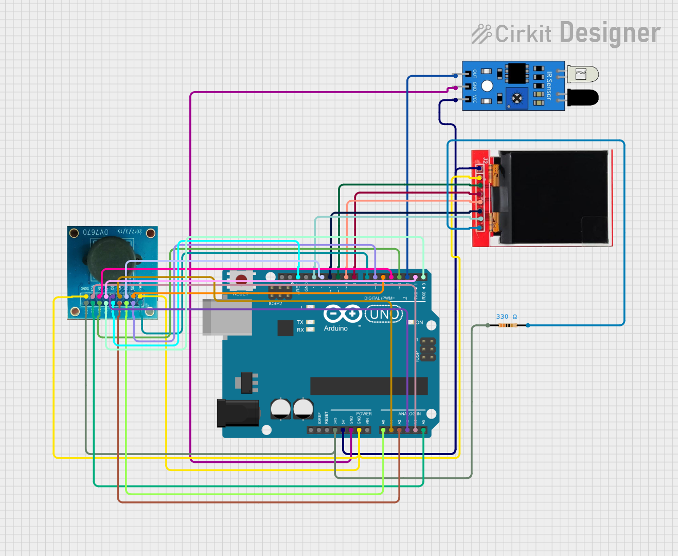
Circuit Documentation
Summary
This document provides a detailed overview of a circuit that includes an OV7670 camera module, a TFT LCD Display ST7735S, an Arduino UNO microcontroller, an infrared (IR) sensor, and a resistor. The circuit is designed to capture images with the OV7670 camera module, display them on the TFT LCD, and possibly react to IR signals. The Arduino UNO serves as the central processing unit, controlling the data flow and interactions between the components.
Component List
OV7670 Camera Module
- Description: A camera module capable of capturing images and video.
- Pins: RET, PWDN, D0-D7, PLK, XLK, VS, HS, SCL, SDA, 3.3V, DGND
TFT LCD Display ST7735S
- Description: A small graphics display with an SPI interface for displaying images and text.
- Pins: Vcc, GND, CS, RESET, A0, SDA, SCK, LED
Arduino UNO
- Description: A microcontroller board based on the ATmega328P, widely used for prototyping and educational purposes.
- Pins: UNUSED, IOREF, Reset, 3.3V, 5V, GND, Vin, A0-A5, SCL, SDA, AREF, D0-D13
IR Sensor
- Description: A sensor that detects infrared light, commonly used in remote control systems.
- Pins: out, gnd, vcc
Resistor (330 Ohms)
- Description: A passive two-terminal electrical component that implements electrical resistance as a circuit element.
- Pins: pin1, pin2
- Resistance: 330 Ohms
Wiring Details
OV7670 Camera Module
- RET connected to Arduino UNO D7
- PWDN and DGND connected to Arduino UNO GND
- D0-D7 connected to Arduino UNO D5, D6, A0, D12, A1, A2, A3, AREF respectively
- PLK connected to Arduino UNO D0
- XLK connected to Arduino UNO D1
- VS connected to Arduino UNO D3
- HS connected to Arduino UNO D4
- SCL connected to Arduino UNO A5
- SDA connected to Arduino UNO A4
- 3.3V connected through a 330 Ohm resistor to Arduino UNO 3.3V
TFT LCD Display ST7735S
- Vcc connected to Arduino UNO 5V
- GND connected to Arduino UNO GND
- CS connected to Arduino UNO D10
- RESET connected to Arduino UNO D8
- A0 connected to Arduino UNO D9
- SDA connected to Arduino UNO D11
- SCK connected to Arduino UNO D13
- LED connected through a 330 Ohm resistor to Arduino UNO 3.3V
Arduino UNO
- GND connected to OV7670 PWDN, DGND, and IR Sensor gnd
- 3.3V connected through a 330 Ohm resistor to OV7670 3.3V and TFT LCD Display LED
- 5V connected to IR Sensor vcc and TFT LCD Display Vcc
- D0-D13 and A0-A5 connected to various pins on the OV7670 and TFT LCD Display as detailed above
IR Sensor
- out connected to Arduino UNO D2
- gnd connected to Arduino UNO GND
- vcc connected to Arduino UNO 5V
Resistor (330 Ohms)
- One end connected to Arduino UNO 3.3V
- The other end connected to OV7670 3.3V and TFT LCD Display LED
Documented Code
Arduino UNO Code (sketch.ino)
void setup() {
  // put your setup code here, to run once:

}

void loop() {
  // put your main code here, to run repeatedly:

}
Additional Notes
- The provided code is a template and does not include specific functionality. It needs to be populated with the setup and loop functions to control the OV7670 camera module, the TFT LCD display, and the IR sensor.
- The code file named "documentation.txt" is empty and does not contain any additional information.