
Circuit Documentation
Summary
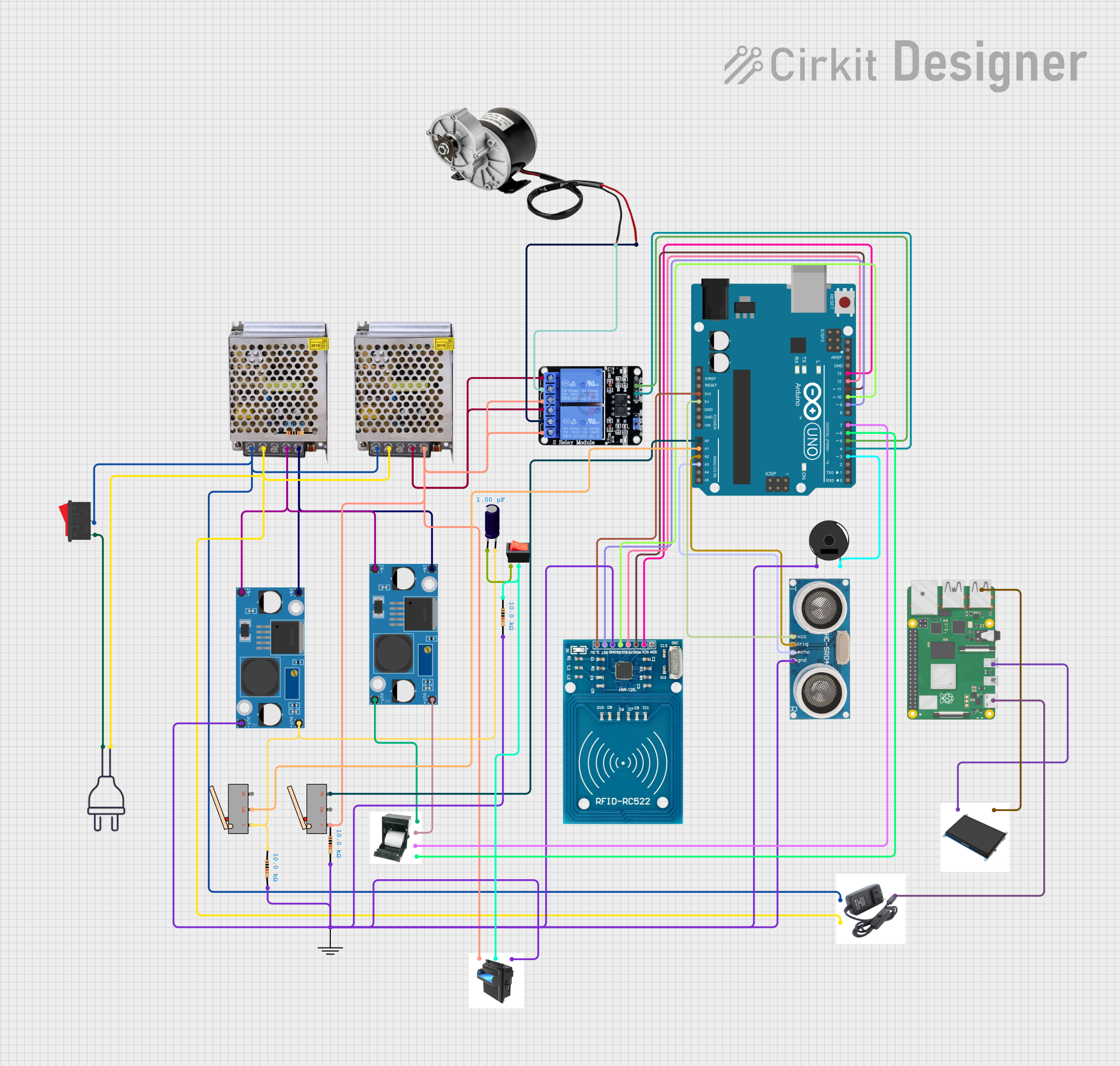
This document provides a detailed overview of a circuit designed to interface various electronic components, including a Raspberry Pi 4 B, an Arduino UNO, power supplies, a relay module, sensors, and other peripherals. The circuit is powered by 12V and 5V power supplies and includes a buck converter for voltage regulation. Communication between components is facilitated through GPIO connections, and the Arduino UNO is programmed to control the circuit's behavior.
Component List
Power Supplies
- POWER SUPPLY 12V 5AMP: Supplies 12V DC power to the circuit.
- POWER SUPPLY 5V 5AMP: Supplies 5V DC power to the circuit.
Control Units
- Raspberry Pi 4 B: A single-board computer with multiple I/O ports used as the main processing unit.
- Arduino UNO: A microcontroller board used for handling various I/O operations within the circuit.
Switches and Relays
- Rocker Switch: A switch used to control the power supply to the circuit.
- Two Channel Relay 5v: A relay module used to control high power devices like motors.
Sensors and Input Devices
- Ultrasonic Sensor: Measures distance using ultrasonic waves.
- RFID-RC522: An RFID reader for contactless communication.
- Limit Switch: A switch that is actuated by the motion of a machine part or presence of an object.
Output Devices
- Thermal Printer: A printer that produces a printed output by heating coated thermochromic paper.
- Piezo Buzzer: An electronic device that produces sound when voltage is applied.
- 10'' Touch Screen LCD: A display screen that also serves as an input device with touch capability.
Power Regulation
- LM2956 Buck Converter DC-DC: A voltage regulator that steps down voltage from a higher level to a lower level.
Miscellaneous
- Electrolytic Capacitor: A capacitor used for filtering and stabilizing the voltage supply.
- Resistor: A passive two-terminal electrical component that implements electrical resistance as a circuit element.
Wiring Details
Raspberry Pi 4 B
- USB 2.0 connected to 10'' Touch Screen LCD HDMI.
- Micro HDMI PORT 1 connected to 10'' Touch Screen LCD 5v.
- USB-C Power Supply connected to adaptor 5v.
Arduino UNO
- D6 connected to Thermal Printer RX.
- D7 connected to Thermal Printer TX.
- 3.3V connected to RFID-RC522 VCC (3.3V).
- 5V connected to Ultrasonic Sensor +VCC.
- A0 connected to Limit Switch NC.
- A1 connected to Limit Switch NO.
- A2 connected to Ultrasonic Sensor Trigger.
- A3 connected to Ultrasonic Sensor Echo.
- D13 connected to RFID-RC522 SCK.
- D12 connected to RFID-RC522 MISO.
- D11 connected to RFID-RC522 MOSI.
- D10 connected to RFID-RC522 IRQ.
- D9 connected to RFID-RC522 RST.
- D3 connected to Piezo Buzzer pin 2.
Power Supplies
- POWER SUPPLY 12V 5AMP 12V-24V Output (DC) connected to LM2956 Buck Converter DC-DC IN+ and another LM2956 Buck Converter DC-DC IN+.
- POWER SUPPLY 12V 5AMP GND (DC) connected to LM2956 Buck Converter DC-DC IN- and another LM2956 Buck Converter DC-DC IN-.
- POWER SUPPLY 5V 5AMP 12V-24V Output (DC) connected to bill acceptor 12v and Two Channel Relay 5v NO2 and NO1.
Relay Module
- Two Channel Relay 5v IN2 connected to Arduino UNO D5.
- Two Channel Relay 5v IN1 connected to Arduino UNO D4.
- Two Channel Relay 5v C2 connected to 250W 12V ELECTRIC MOTOR BRUSH MOTOR DC NEGATIF.
- Two Channel Relay 5v C1 connected to 250W 12V ELECTRIC MOTOR BRUSH MOTOR DC POSITIF.
Sensors and Input Devices
- Ultrasonic Sensor GND connected to GND.
- RFID-RC522 GND connected to GND.
- bill acceptor GND connected to GND.
Output Devices
- Thermal Printer + connected to LM2956 Buck Converter DC-DC OUT+.
- Thermal Printer - connected to LM2956 Buck Converter DC-DC OUT-.
Power Regulation
- LM2956 Buck Converter DC-DC OUT+ connected to Thermal Printer + and Electrolytic Capacitor +.
Miscellaneous
- Electrolytic Capacitor - connected to rocker switch input.
- Resistor pin1 connected to bill acceptor out and rocker switch output.
Documented Code
Arduino UNO (fb3915ea-f869-4c6b-a7e3-9b845498b9ce)
void setup() {
  // put your setup code here, to run once:

}

void loop() {
  // put your main code here, to run repeatedly:

}
Note: The provided code for the Arduino UNO is a template with empty setup and loop functions. Additional code is required to implement the desired functionality.