
Arduino Mega 2560 LED Control System with Multi-Color Indicators
View and Edit Project In Cirkit Designer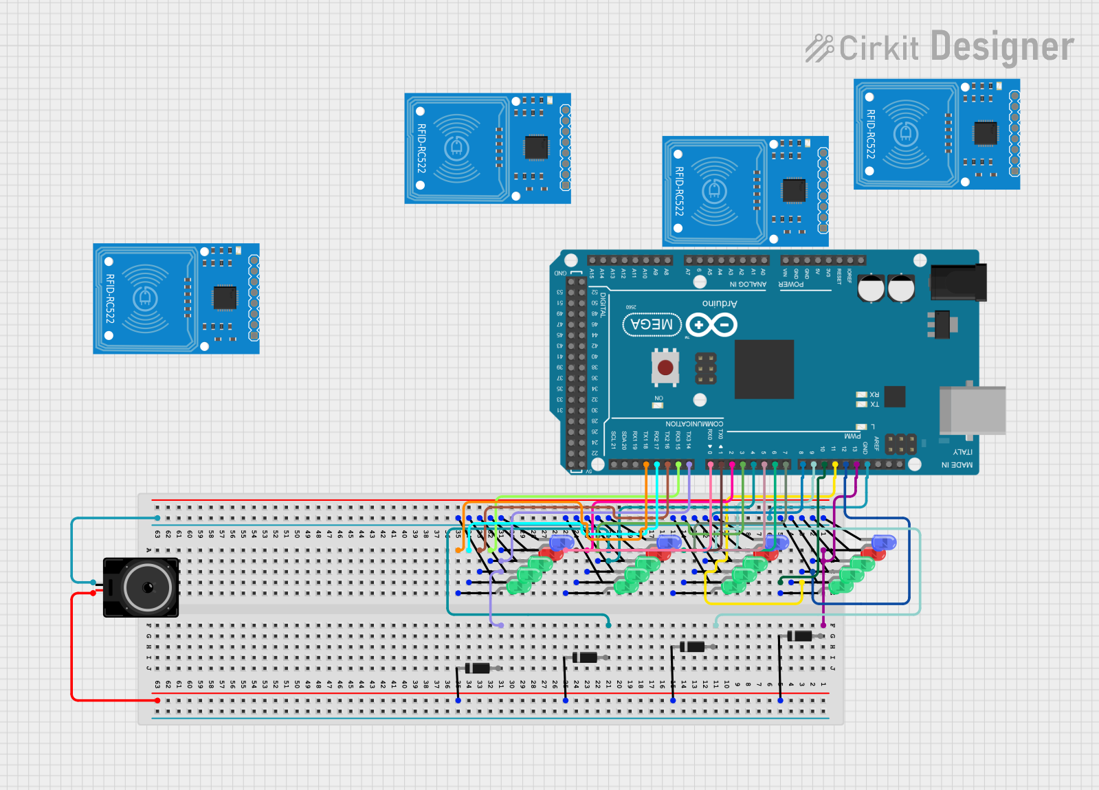
Circuit Documentation
Summary
This circuit involves an Arduino Mega 2560 microcontroller connected to multiple LEDs of various colors and a loudspeaker. The LEDs are controlled via the digital pins of the Arduino, and the loudspeaker is connected through a series of diodes.
Component List
Arduino Mega 2560
- Description: A microcontroller board based on the ATmega2560.
- Pins: IOREF, RESET, 3V3, 5V, GND, VIN, A0-A15, D0-D53, AREF, SDA, SCL
LED: Two Pin (red)
- Description: A red LED with two pins: anode and cathode.
- Pins: cathode, anode
LED: Two Pin (green)
- Description: A green LED with two pins: anode and cathode.
- Pins: cathode, anode
LED: Two Pin (blue)
- Description: A blue LED with two pins: anode and cathode.
- Pins: cathode, anode
Loudspeaker
- Description: A loudspeaker with two pins.
- Pins: pin1, pin2
Diode
- Description: A diode with two pins: cathode and anode.
- Pins: cathode, anode
RFID-RC522
- Description: An RFID module with multiple pins for communication.
- Pins: SDA, SCK, MOSI, MISO, IRQ, GND, RST, 3.3V
Wiring Details
Arduino Mega 2560
- D18/TX1: Connected to the anode of a green LED.
- D17 PWM/RX2: Connected to the anode of a green LED.
- D16 PWM/TX2: Connected to the anode of a green LED.
- D15/RX3: Connected to the anode of a red LED.
- D14/TX3: Connected to the anode of a blue LED.
- D0 RX0: Connected to the anode of a green LED.
- D1 TX0: Connected to the anode of a green LED.
- D2 PWM: Connected to the anode of a green LED.
- D3 PWM: Connected to the anode of a red LED.
- D4 PWM: Connected to the anode of a blue LED.
- D5 PWM: Connected to the anode of a green LED.
- D6 PWM: Connected to the anode of a green LED.
- D7 PWM: Connected to the anode of a green LED.
- D8 PWM: Connected to the anode of a red LED.
- D9 PWM: Connected to the anode of a blue LED.
- D10 PWM: Connected to the anode of a green LED.
- D11 PWM: Connected to the anode of a green LED.
- D12 PWM: Connected to the anode of a red LED.
- D13 PWM: Connected to the anode of a blue LED.
- GND: Connected to the cathodes of all LEDs and pin1 of the loudspeaker.
LED: Two Pin (red)
- Anode: Connected to D15/RX3, D3 PWM, D8 PWM, D12 PWM of the Arduino Mega 2560.
- Cathode: Connected to GND of the Arduino Mega 2560.
LED: Two Pin (green)
- Anode: Connected to D18/TX1, D17 PWM/RX2, D16 PWM/TX2, D0 RX0, D1 TX0, D2 PWM, D5 PWM, D6 PWM, D7 PWM, D10 PWM, D11 PWM of the Arduino Mega 2560.
- Cathode: Connected to GND of the Arduino Mega 2560.
LED: Two Pin (blue)
- Anode: Connected to D14/TX3, D4 PWM, D9 PWM, D13 PWM of the Arduino Mega 2560.
- Cathode: Connected to GND of the Arduino Mega 2560.
Loudspeaker
- Pin1: Connected to GND of the Arduino Mega 2560.
- Pin2: Connected to the cathodes of all diodes.
Diode
- Cathode: Connected to pin2 of the loudspeaker.
- Anode: Not connected in the provided net list.
RFID-RC522
- SDA, SCK, MOSI, MISO, IRQ, GND, RST, 3.3V: Not connected in the provided net list.
Code Documentation
Arduino Mega 2560 Code
sketch.ino
void setup() {
  // put your setup code here, to run once:

}

void loop() {
  // put your main code here, to run repeatedly:

}
documentation.txt
This document provides a comprehensive overview of the circuit, including a detailed list of components, their connections, and the code used in the microcontroller.