
Arduino Mega 2560 Smart Light System with Photocells and RGB LED Strip
View and Edit Project In Cirkit Designer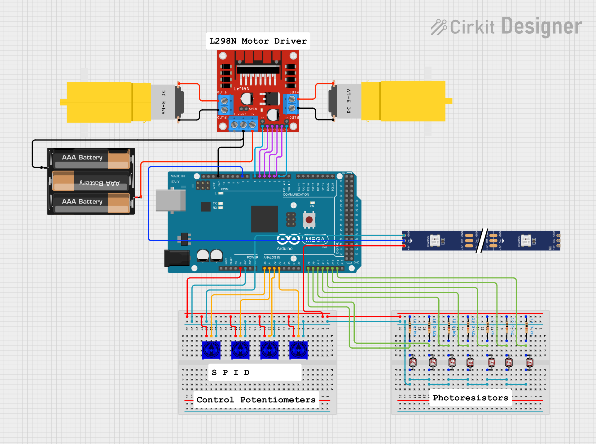
Circuit Documentation
Summary
This circuit involves an Arduino Mega 2560 microcontroller interfacing with multiple components including trimming potentiometers, photocells (LDRs), resistors, a WS2812 RGB LED strip, an L298N DC motor driver, and hobby motors. The circuit is designed to read analog signals from the potentiometers and photocells, control the LED strip, and drive the motors using the motor driver.
Component List
TSR-3386UT Square Trimming Potentiometer
- Description: Trimming potentiometer used for adjusting resistance.
- Pins: Leg1, wiper, Leg2
Photocell (LDR)
- Description: Light-dependent resistor used to measure light intensity.
- Pins: pin 0, pin 1
Resistor
- Description: Fixed resistor with a resistance of 10k Ohms.
- Pins: pin1, pin2
- Properties:
- Resistance: 10k Ohms
Arduino Mega 2560
- Description: Microcontroller board based on the ATmega2560.
- Pins: IOREF, RESET, 3V3, 5V, GND, VIN, A0-A15, D0-D53, PWM pins, AREF, SDA, SCL
WS2812 RGB LED strip
- Description: Addressable RGB LED strip.
- Pins: DIN, 5V, GND, DO
L298N DC motor driver
- Description: Dual H-Bridge motor driver.
- Pins: OUT1, OUT2, 12V, GND, 5V, OUT3, OUT4, 5V-ENA-JMP-I, 5V-ENA-JMP-O, +5V-J1, +5V-J2, ENA, IN1, IN2, IN3, IN4, ENB
Motor amarillo motorreductor hobby
- Description: Hobby motor with gearbox.
- Pins: vcc, GND
3xAABattery
- Description: Battery pack providing power to the circuit.
- Pins: VCC, GND
Wiring Details
TSR-3386UT Square Trimming Potentiometer
Leg2 is connected to:
- Leg2 of other trimming potentiometers
- GND of WS2812 RGB LED strip
- GND of Arduino Mega 2560
- pin 1 of all photocells
wiper is connected to:
- A3 of Arduino Mega 2560 (for one potentiometer)
- A2 of Arduino Mega 2560 (for another potentiometer)
- A1 of Arduino Mega 2560 (for another potentiometer)
- A0 of Arduino Mega 2560 (for another potentiometer)
Leg1 is connected to:
- Leg1 of other trimming potentiometers
- pin1 of all resistors
- 5V of WS2812 RGB LED strip
- 5V of Arduino Mega 2560
Photocell (LDR)
pin 0 is connected to:
- pin2 of corresponding resistors
- A14 to A8 of Arduino Mega 2560 (one for each photocell)
pin 1 is connected to:
- GND of Arduino Mega 2560
- GND of WS2812 RGB LED strip
- Leg2 of all trimming potentiometers
Resistor
pin1 is connected to:
- Leg1 of all trimming potentiometers
- pin1 of other resistors
- 5V of WS2812 RGB LED strip
- 5V of Arduino Mega 2560
pin2 is connected to:
- pin 0 of corresponding photocells
- A14 to A8 of Arduino Mega 2560 (one for each resistor)
Arduino Mega 2560
GND is connected to:
- GND of WS2812 RGB LED strip
- GND of L298N DC motor driver
- GND of 3xAABattery
- pin 1 of all photocells
5V is connected to:
- 5V of WS2812 RGB LED strip
- pin1 of all resistors
- Leg1 of all trimming potentiometers
A0 to A3 are connected to:
- wiper of corresponding trimming potentiometers
A8 to A14 are connected to:
- pin 0 of corresponding photocells
- pin2 of corresponding resistors
D2 PWM to D7 PWM are connected to:
- ENB, IN4, IN3, IN2, IN1, ENA of L298N DC motor driver
D9 PWM is connected to:
- DIN of WS2812 RGB LED strip
WS2812 RGB LED strip
DIN is connected to:
- D9 PWM of Arduino Mega 2560
5V is connected to:
- 5V of Arduino Mega 2560
- pin1 of all resistors
- Leg1 of all trimming potentiometers
GND is connected to:
- GND of Arduino Mega 2560
- GND of L298N DC motor driver
- pin 1 of all photocells
- Leg2 of all trimming potentiometers
L298N DC motor driver
ENB is connected to:
- D2 PWM of Arduino Mega 2560
IN4 is connected to:
- D3 PWM of Arduino Mega 2560
IN3 is connected to:
- D4 PWM of Arduino Mega 2560
IN2 is connected to:
- D5 PWM of Arduino Mega 2560
IN1 is connected to:
- D6 PWM of Arduino Mega 2560
ENA is connected to:
- D7 PWM of Arduino Mega 2560
GND is connected to:
- GND of Arduino Mega 2560
- GND of 3xAABattery
OUT1 is connected to:
- GND of one hobby motor
OUT2 is connected to:
- vcc of the same hobby motor
OUT3 is connected to:
- GND of another hobby motor
OUT4 is connected to:
- vcc of the same hobby motor
5V is connected to:
- VCC of 3xAABattery
Motor amarillo motorreductor hobby
vcc is connected to:
- OUT2 of L298N DC motor driver (for one motor)
- OUT4 of L298N DC motor driver (for another motor)
GND is connected to:
- OUT1 of L298N DC motor driver (for one motor)
- OUT3 of L298N DC motor driver (for another motor)
3xAABattery
VCC is connected to:
- 5V of L298N DC motor driver
GND is connected to:
- GND of L298N DC motor driver
- GND of Arduino Mega 2560
Documented Code
Arduino Mega 2560 Code
void setup() {
  // put your setup code here, to run once:

}

void loop() {
  // put your main code here, to run repeatedly:

}
Additional Documentation
// This file is intended for additional documentation purposes.
This documentation provides a comprehensive overview of the circuit, including a detailed component list, wiring details, and the code used in the Arduino Mega 2560 microcontroller.