
Circuit Documentation
Summary
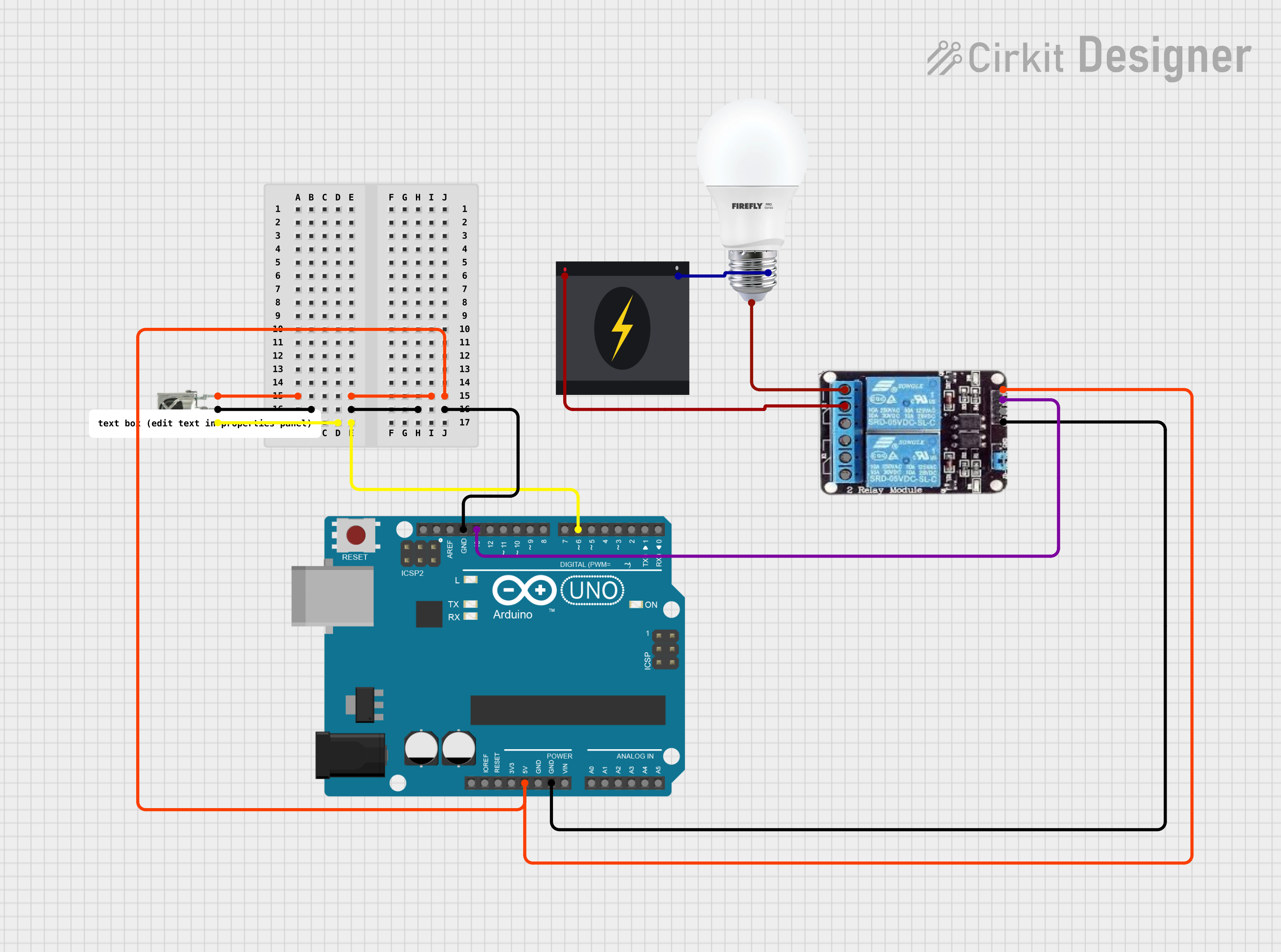
This circuit integrates an Arduino UNO microcontroller with a 2-channel relay module, a VS1838B IR receiver, and a bulb controlled by a 240V power source. The Arduino UNO is used as the central processing unit to interpret IR signals received by the VS1838B IR receiver and control the relay module accordingly. The relay module switches the high-voltage circuit for the bulb, allowing the bulb to be turned on or off based on the IR commands received.
Component List
Arduino UNO
- Microcontroller board based on the ATmega328P
- It has 14 digital input/output pins, 6 analog inputs, a 16 MHz quartz crystal, a USB connection, a power jack, an ICSP header, and a reset button.
2-channel Relay
- A module with two relays that can control high voltage/high current devices.
- It has normally closed (NC), common (COM), and normally open (NO) terminals for each relay, along with VCC and GND for power, and IN1 and IN2 for control signals.
BULB
- An electric light with two terminals: positive (+) and negative (-).
- It is controlled by the relay and powered by a 240V power source.
VS1838B IR Receiver
- An infrared receiver that can detect IR signals from a remote control.
- It has three pins: OUT (signal output), GND, and VCC.
240V Power Source
- Provides the high voltage required for the bulb.
- It has two terminals: Live and Neutral.
Wiring Details
Arduino UNO
- 5V pin is connected to the VCC of the VS1838B IR Receiver and the VCC of the 2-channel relay.
- GND pin is connected to the GND of the VS1838B IR Receiver and the GND of the 2-channel relay.
- D13 pin is connected to the IN2 of the 2-channel relay.
- D6 pin is connected to the OUT of the VS1838B IR Receiver.
2-channel Relay
- VCC is connected to the 5V of the Arduino UNO.
- GND is connected to the GND of the Arduino UNO.
- IN2 is connected to the D13 of the Arduino UNO.
- COM is connected to the Live terminal of the 240V Power Source.
- NO is connected to the positive (+) terminal of the BULB.
BULB
- Positive (+) terminal is connected to the NO of the 2-channel relay.
- Negative (-) terminal is connected to the Neutral terminal of the 240V Power Source.
VS1838B IR Receiver
- VCC is connected to the 5V of the Arduino UNO.
- GND is connected to the GND of the Arduino UNO.
- OUT is connected to the D6 of the Arduino UNO.
240V Power Source
- Live terminal is connected to the COM of the 2-channel relay.
- Neutral terminal is connected to the negative (-) terminal of the BULB.
Documented Code
Arduino UNO Code (sketch.ino)
void setup() {
  // put your setup code here, to run once:

}

void loop() {
  // put your main code here, to run repeatedly:

}
Note: The provided code is a template and does not contain any functional code to control the relay or read the IR receiver. The user must implement the setup and loop functions to initialize the pins and handle the IR signals to control the relay.