
ESP32-Based Multi-Sensor Monitoring System with GSM Notification and Power Management
View and Edit Project In Cirkit Designer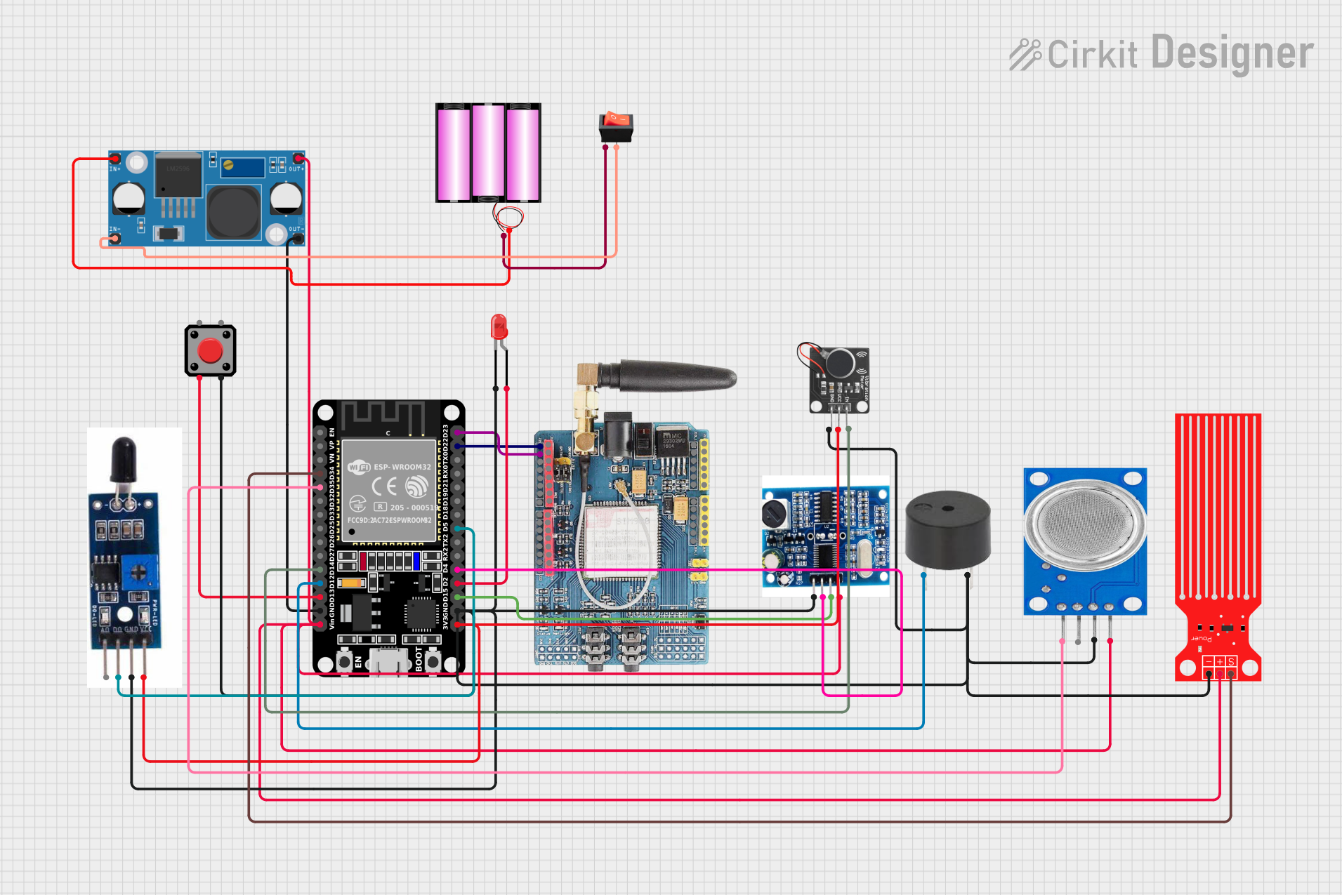
Circuit Documentation
Summary
The circuit in question is designed to interface various sensors and modules with an ESP32 microcontroller. The sensors include a water level sensor, an MQ135 air quality sensor, a heat flame sensor, an ultrasonic ranging module, and a PWM vibration motor sensor module. Additionally, the circuit incorporates a GSM SIM900 module for cellular communication, a buzzer, a pushbutton, an LED, and a rocker switch for user interaction. Power management is handled by a 12V battery and an LM2956 buck converter to step down the voltage for the components. The ESP32 serves as the central processing unit, reading sensor data, controlling outputs, and managing communication.
Component List
ESP32 (30 pin)
- A microcontroller with WiFi and Bluetooth capabilities, featuring a variety of digital and analog pins for interfacing with peripherals.
GSM SIM900
- A GSM/GPRS module that allows cellular network communication for sending SMS, making calls, or connecting to the internet.
Buzzer
- An audio signaling device that can be used to provide audible alerts or feedback.
MQ135
- An air quality sensor capable of detecting a wide range of gases, including NH3, NOx, alcohol, benzene, smoke, and CO2.
Water Level Sensor
- A sensor used to detect the level of water in a tank or other container.
Heat Flame Sensor
- A sensor designed to detect the presence of fire or other heat sources.
Ultrasonic Ranging Module
- A module that measures distance by emitting ultrasonic waves and timing their reflection from objects.
Pushbutton
- A simple switch mechanism for controlling some aspect of a machine or a process.
Rocker Switch
- An on/off switch that rocks (rather than trips) when pressed.
LED: Two Pin (red)
- A basic red light-emitting diode used for indication purposes.
Battery 12V
- A 12-volt battery that provides power to the circuit.
LM2956 Buck Converter DC-DC
- A DC-DC converter that steps down voltage from a higher level to a lower level.
PWM Vibration Motor Sensor Module Switch
- A module that controls a vibration motor with Pulse Width Modulation (PWM) for varying the intensity of vibration.
Wiring Details
ESP32 (30 pin)
D34connected to Water Level SensorSIGD35connected to MQ135D0D14connected to PWM Vibration Motor Sensor Module SwitchSignalD12connected to BuzzerPIND13connected to PushbuttonPin 2GNDconnected to LM2956 Buck Converter DC-DCOUT-Vinconnected to LM2956 Buck Converter DC-DCOUT+D23connected to GSM SIM900D1D22connected to GSM SIM900D0D5connected to Heat Flame SensorDOD4connected to Ultrasonic Ranging ModuleEchoD2connected to LEDanodeD15connected to Ultrasonic Ranging ModuleTrig3V3connected to PWM Vibration Motor Sensor Module SwitchVccand Heat Flame SensorVCC
GSM SIM900
D1connected to ESP32D23D0connected to ESP32D22
Buzzer
PINconnected to ESP32D12GNDconnected to common ground
MQ135
D0connected to ESP32D35VCCconnected to LM2956 Buck Converter DC-DCOUT+GNDconnected to common ground
Water Level Sensor
SIGconnected to ESP32D34VCCconnected to LM2956 Buck Converter DC-DCOUT+GNDconnected to common ground
Heat Flame Sensor
DOconnected to ESP32D5VCCconnected to ESP323V3GNDconnected to common ground
Ultrasonic Ranging Module
Echoconnected to ESP32D4Trigconnected to ESP32D15Vccconnected to LM2956 Buck Converter DC-DCOUT+GNDconnected to common ground
Pushbutton
Pin 2connected to ESP32D13Pin 3connected to common ground
Rocker Switch
outputconnected to LM2956 Buck Converter DC-DCIN-inputconnected to Battery 12V-
LED: Two Pin (red)
anodeconnected to ESP32D2cathodeconnected to common ground
Battery 12V
+connected to LM2956 Buck Converter DC-DCIN+-connected to Rocker Switchinput
LM2956 Buck Converter DC-DC
OUT+connected to ESP32Vin, Water Level SensorVCC, Ultrasonic Ranging ModuleVcc, and MQ135VCCOUT-connected to ESP32GNDIN+connected to Battery 12V+IN-connected to Rocker Switchoutput
PWM Vibration Motor Sensor Module Switch
Signalconnected to ESP32D14Vccconnected to ESP323V3Groundconnected to common ground
Documented Code
No code has been provided for the microcontroller. The documentation of the code would typically include descriptions of the functions, algorithms, and logic used to read sensor data, control outputs, and manage communication with the GSM module. It would also include any libraries used, initialization routines, and the main loop logic. Since no code is available, this section cannot be completed.