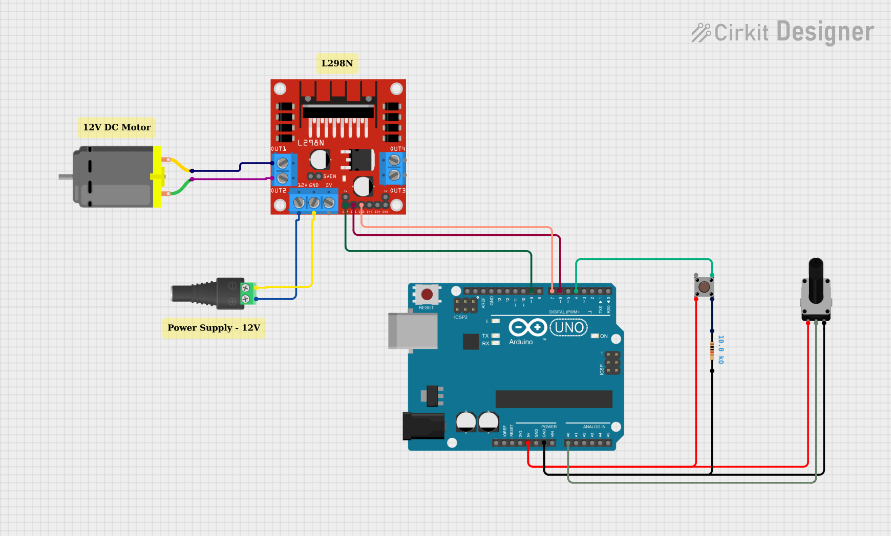
Arduino-Controlled DC Motor with Speed Adjustment and Pushbutton Toggle

Circuit Documentation
Summary
This circuit is designed to control a DC motor using an L298N motor driver module, with an Arduino UNO as the microcontroller. The control inputs for the motor are provided by a pushbutton and a rotary potentiometer. The pushbutton toggles the motor on and off, while the potentiometer adjusts the motor's speed. The circuit is powered by a 2.1mm Barrel Jack with Terminal Block, which supplies the necessary voltage to the motor driver and the Arduino UNO. A resistor is used in conjunction with the pushbutton to provide a stable input signal to the Arduino.
Component List
DC Motor
- Description: A standard DC motor used for converting electrical energy into mechanical motion.
- Purpose: The primary actuator in the circuit, responsible for performing mechanical work when powered.
L298N DC Motor Driver
- Description: An integrated circuit used for controlling the direction and speed of DC motors.
- Purpose: To drive the DC motor based on signals from the Arduino UNO.
2.1mm Barrel Jack with Terminal Block
- Description: A power connector that allows for easy connection to an external power supply.
- Purpose: To provide power to the motor driver and the Arduino UNO.
Pushbutton
- Description: A simple switch mechanism for controlling a circuit.
- Purpose: To toggle the motor on and off.
Resistor
- Description: A passive two-terminal electrical component that implements electrical resistance.
- Purpose: To work with the pushbutton for debouncing and providing a stable input signal.
Rotary Potentiometer
- Description: A three-terminal resistor with a rotating contact that forms an adjustable voltage divider.
- Purpose: To adjust the motor speed by varying the voltage input to the Arduino's analog pin.
Arduino UNO
- Description: A microcontroller board based on the ATmega328P.
- Purpose: To process input signals from the pushbutton and potentiometer and control the motor driver accordingly.
Wiring Details
DC Motor
- Connected to the L298N motor driver's OUT1 and OUT2.
L298N DC Motor Driver
- OUT1 and OUT2 connected to the DC Motor.
- 12V and GND connected to the 2.1mm Barrel Jack with Terminal Block for power.
- ENA, IN1, and IN2 connected to the Arduino UNO for motor control signals.
2.1mm Barrel Jack with Terminal Block
- POS and NEG connected to the L298N motor driver for power distribution.
Pushbutton
- One output connected to the Arduino UNO for toggling the motor state.
- The other output connected to the Resistor for debouncing.
Resistor
- Connected between the Pushbutton and the Rotary Potentiometer to form part of the debouncing circuit.
Rotary Potentiometer
- Wiper connected to the Arduino UNO for speed control input.
- One leg connected to the Arduino's 5V output, and the other leg connected to GND.
Arduino UNO
- Digital and analog pins connected to the L298N motor driver, Pushbutton, and Rotary Potentiometer to control the motor and read inputs.
Documented Code
/*
  Motor Control Sketch
  This Arduino sketch is designed to control a DC motor using an L298N motor driver.
  It reads input from a pushbutton and a potentiometer to toggle the motor on/off and control its speed.

  The pushbutton is used to start and stop the motor. When the button is pressed, the motor's
  state is toggled between on and off. A simple debounce mechanism is implemented to prevent
  misreading the pushbutton input.

  The potentiometer is used to adjust the motor speed. The analog reading from the potentiometer
  is mapped to a PWM value that controls the speed of the motor when it is on.

  Connections:
  - L298N ENA connected to Arduino Digital Pin 9 (motorEnablePin)
  - L298N IN1 connected to Arduino Digital Pin 6 (motorInput1)
  - L298N IN2 connected to Arduino Digital Pin 7 (motorInput2)
  - Pushbutton output connected to Arduino Digital Pin 4 (pushButtonPin)
  - Potentiometer wiper connected to Arduino Analog Pin A0 (potPin)

  The code assumes the pushbutton provides a HIGH signal when pressed.
*/

// Define the motor control pins
const int motorEnablePin = 9; // ENA on L298N connected to D9 on Arduino
const int motorInput1 = 6;    // IN1 on L298N connected to D6 on Arduino
const int motorInput2 = 7;    // IN2 on L298N connected to D7 on Arduino

// Define the pushbutton pin
const int pushButtonPin = 4;  // Pushbutton output connected to D4 on Arduino

// Define the potentiometer pin
const int potPin = A0;        // Potentiometer wiper connected to A0 on Arduino

// Variables to keep track of motor state and speed
bool motorEnabled = false;
int motorSpeed = 0;

void setup() {
  // Set the motor control pins as outputs
  pinMode(motorEnablePin, OUTPUT);
  pinMode(motorInput1, OUTPUT);
  pinMode(motorInput2, OUTPUT);

  // Set the pushbutton pin as an input
  pinMode(pushButtonPin, INPUT);

  // Initialize the motor control pins
  digitalWrite(motorEnablePin, LOW);
  digitalWrite(motorInput1, LOW);
  digitalWrite(motorInput2, LOW);
}

void loop() {
  // Read the pushbutton state
  bool buttonState = digitalRead(pushButtonPin);

  // If the button is pressed, toggle the motor state
  if (buttonState == HIGH) {
    motorEnabled = !motorEnabled;
    delay(200); // Debounce delay to prevent misreading the pushbutton input
  }

  // Read the potentiometer value
  int potValue = analogRead(potPin);
  // Map the potentiometer value to a motor speed (0-255)
  motorSpeed = map(potValue, 0, 1023, 0, 255);

  // Control the motor based on the motorEnabled state and motorSpeed
  if (motorEnabled) {
    // Set the motor to spin in one direction
    digitalWrite(motorInput1, HIGH);
    digitalWrite(motorInput2, LOW);
    // Set the motor speed using PWM
    analogWrite(motorEnablePin, motorSpeed);
  } else {
    // Turn off the motor
    digitalWrite(motorInput1, LOW);
    digitalWrite(motorInput2, LOW);
    analogWrite(motorEnablePin, 0);
  }
}
This code is responsible for reading the state of the pushbutton and the potentiometer, toggling the motor's state, and adjusting its speed accordingly. The debounce delay ensures that the pushbutton's state is read correctly without false triggering. The potentiometer's analog value is mapped to a PWM value to control the motor's speed.