Cirkit Designer
Your all-in-one circuit design IDE
Home /
Project Documentation
ESP32-Based NFC Interface with OLED Display and Indicators
Circuit Documentation
Summary
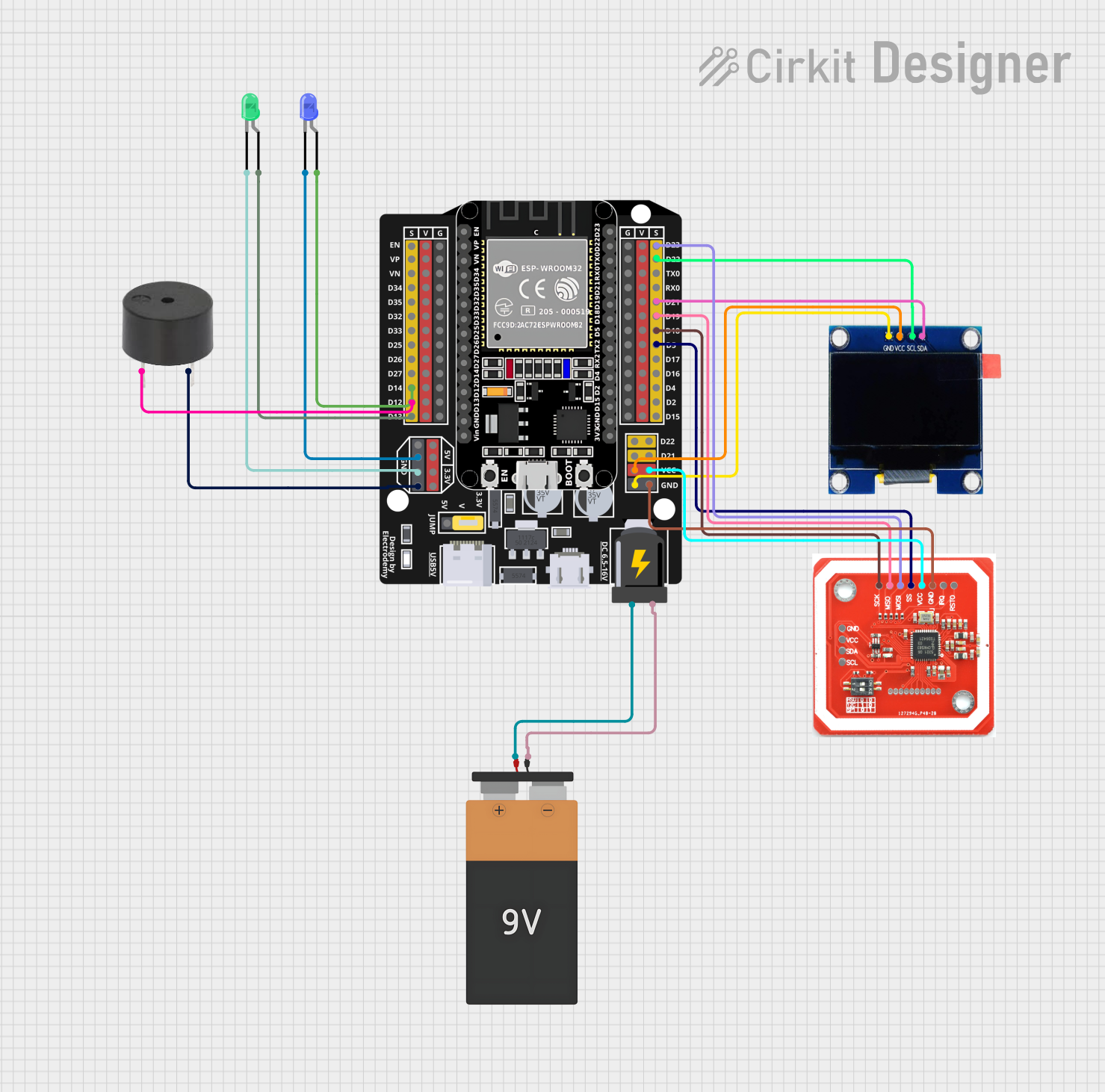
This document provides a detailed overview of a circuit designed to interface various components with an ESP32 Expansion Board. The circuit includes a 9V battery for power, a buzzer, two LEDs (green and blue), an NFC/RFID reader (PN532), and an OLED 1.3" display. The ESP32 serves as the central microcontroller unit, managing input/output operations and communication with the NFC/RFID reader and the OLED display. The LEDs and buzzer are used for signaling purposes.
Component List
Buzzer
- Description: A simple buzzer for audible alerts.
- Pins: PIN, GND
LED: Two Pin (Green)
- Description: A green LED for visual indication.
- Pins: Cathode, Anode
LED: Two Pin (Blue)
- Description: A blue LED for visual indication.
- Pins: Cathode, Anode
ESP32 - Expansion Board
- Description: The main microcontroller board for controlling the circuit.
- Pins: +, -, EN, VP, VN, D34, D32, D33, D25, D26, D27, D14, D12, D13, D23, D22, TX0, RX0, D21, D19, D18, D5, D17, D16, D4, D2, D15, VCC, G, 5V, 3.3V, V
Battery 9V
- Description: Provides power to the circuit.
- Pins: VCC, GND
NFC/RFID reader PN532
- Description: A reader for NFC/RFID communication.
- Pins: GND, VCC, SDA, SCL, SCK, MISO, MOSI, SS, IRQ, RSTO
OLED 1.3"
- Description: A small display for visual output.
- Pins: GND, VCC, SCL, SDA
Wiring Details
Buzzer
- PIN connected to ESP32 Expansion Board D12
- GND connected to ESP32 Expansion Board G
LED: Two Pin (Green)
- Anode connected to ESP32 Expansion Board D13
- Cathode connected to ESP32 Expansion Board G
LED: Two Pin (Blue)
- Anode connected to ESP32 Expansion Board D14
- Cathode connected to ESP32 Expansion Board G
ESP32 - Expansion Board
- "+" connected to Battery 9V VCC
- "-" connected to Battery 9V GND
- D14 connected to Blue LED Anode
- D12 connected to Buzzer PIN
- D13 connected to Green LED Anode
- D23 connected to NFC/RFID reader PN532 MOSI
- D22 connected to OLED 1.3" SCL
- D21 connected to OLED 1.3" SDA
- D19 connected to NFC/RFID reader PN532 MISO
- D18 connected to NFC/RFID reader PN532 SCK
- D5 connected to NFC/RFID reader PN532 SS
- VCC connected to OLED 1.3" VCC and NFC/RFID reader PN532 VCC
- G connected to OLED 1.3" GND, NFC/RFID reader PN532 GND, Blue LED Cathode, Green LED Cathode, and Buzzer GND
Battery 9V
- VCC connected to ESP32 Expansion Board +
- GND connected to ESP32 Expansion Board -
NFC/RFID reader PN532
- MOSI connected to ESP32 Expansion Board D23
- MISO connected to ESP32 Expansion Board D19
- SCK connected to ESP32 Expansion Board D18
- SS connected to ESP32 Expansion Board D5
- VCC connected to ESP32 Expansion Board VCC
- GND connected to ESP32 Expansion Board G
OLED 1.3"
- SCL connected to ESP32 Expansion Board D22
- SDA connected to ESP32 Expansion Board D21
- VCC connected to ESP32 Expansion Board VCC
- GND connected to ESP32 Expansion Board G
Documented Code
OLED 1.3" Display Code (sketch.ino)
void setup() {
  // put your setup code here, to run once:

}

void loop() {
  // put your main code here, to run repeatedly:

}
Note: The provided code for the OLED 1.3" display is a template with empty setup and loop functions. Additional functionality should be implemented as per the requirements of the application.
OLED 1.3" Display Documentation (documentation.txt)
No additional documentation was provided for the OLED 1.3" display.
End of Documentation