
ESP8266 NodeMCU Controlled Ultrasonic Sensor with Relay and I2C LCD Display
View and Edit Project In Cirkit Designer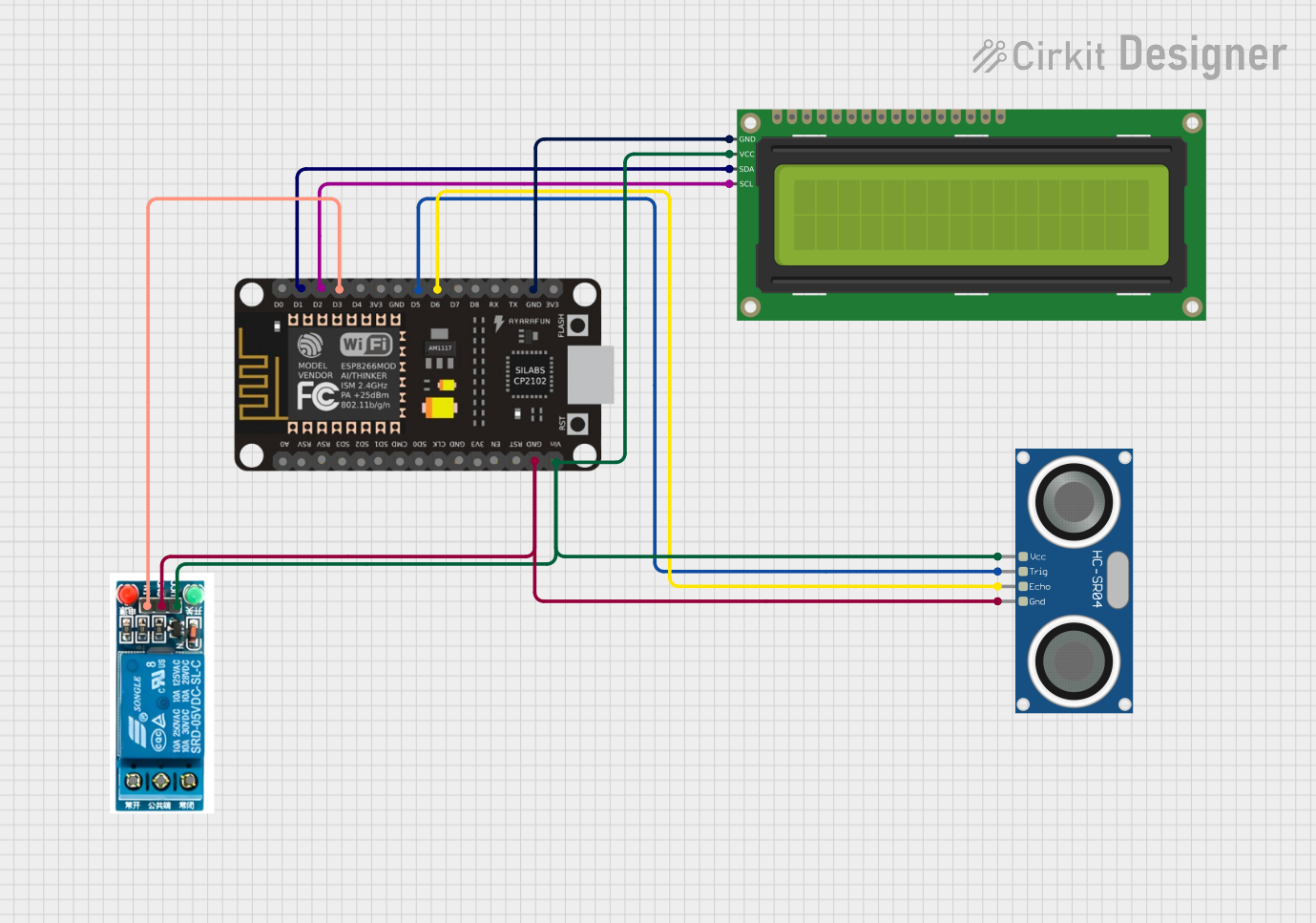
Circuit Documentation
Summary of the Circuit
This circuit integrates an ESP8266 NodeMCU microcontroller with an HC-SR04 Ultrasonic Sensor, a 5V relay, and a 16x2 I2C LCD display. The ESP8266 NodeMCU serves as the central processing unit, controlling the relay and reading distance measurements from the ultrasonic sensor. The LCD display is used to output information, likely the distance measurements or system status. The relay can be used to control a higher power device, triggered by the microcontroller based on sensor inputs or other logic. The circuit is designed to share a common ground and is powered through the NodeMCU's VIN pin, which distributes power to the other components.
Component List
ESP8266 NodeMCU
- Description: A Wi-Fi capable microcontroller module with an ESP8266 chip.
- Pins: D0, D1, D2, D3, D4, 3V3, GND, D5, D6, D7, D8, RX, TX, A0, RSV, SD3, SD2, SD1, CMD, SD0, CLK, EN, RST, VIN
HC-SR04 Ultrasonic Sensor
- Description: A sensor for measuring distance via ultrasonic sound waves.
- Pins: VCC, TRIG, ECHO, GND
5V Relay
- Description: An electromechanical switch that allows a low-power circuit to control a higher power circuit.
- Pins: Normally Open, Common terminal, Normally Closed, In, GND, VCC
16x2 I2C LCD
- Description: A liquid crystal display capable of showing 16 characters in 2 rows with an I2C interface.
- Pins: GND, VCC, SDA, SCL
Wiring Details
ESP8266 NodeMCU
- D1 (SDA) -> 16x2 I2C LCD (SDA)
- D2 (SCL) -> 16x2 I2C LCD (SCL)
- D3 -> 5V Relay (In)
- D5 (TRIG) -> HC-SR04 Ultrasonic Sensor (TRIG)
- D6 (ECHO) -> HC-SR04 Ultrasonic Sensor (ECHO)
- GND -> 16x2 I2C LCD (GND), HC-SR04 Ultrasonic Sensor (GND), 5V Relay (GND)
- VIN -> 16x2 I2C LCD (VCC), HC-SR04 Ultrasonic Sensor (VCC), 5V Relay (VCC)
HC-SR04 Ultrasonic Sensor
- VCC -> ESP8266 NodeMCU (VIN)
- TRIG -> ESP8266 NodeMCU (D5)
- ECHO -> ESP8266 NodeMCU (D6)
- GND -> ESP8266 NodeMCU (GND)
5V Relay
- In -> ESP8266 NodeMCU (D3)
- GND -> ESP8266 NodeMCU (GND)
- VCC -> ESP8266 NodeMCU (VIN)
16x2 I2C LCD
- SDA -> ESP8266 NodeMCU (D1)
- SCL -> ESP8266 NodeMCU (D2)
- GND -> ESP8266 NodeMCU (GND)
- VCC -> ESP8266 NodeMCU (VIN)
Documented Code
No code has been provided for the microcontroller. The documentation of the code would typically include a description of the functionality, setup and loop functions, and any functions or libraries used to control the components in the circuit. Since no code is available, this section cannot be completed. If code becomes available, it should be documented here with comments explaining the purpose and functionality of each part of the code.