
Circuit Documentation
Summary
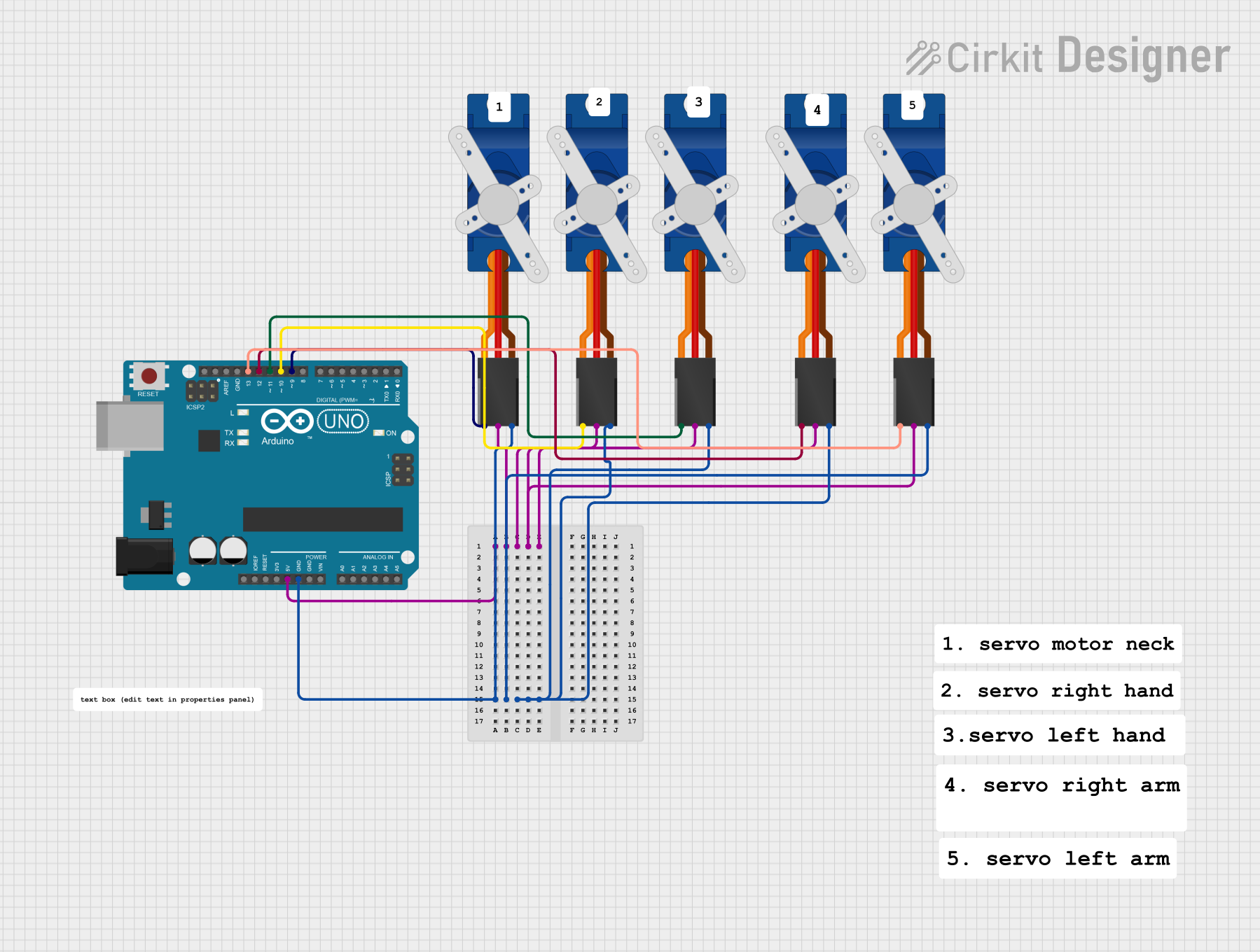
This circuit is designed to control multiple Tower Pro SG90 servos using an Arduino UNO microcontroller. The servos are connected to the Arduino's digital pins and are powered by the Arduino's 5V output. The ground pins of all servos are also connected to the Arduino's ground. This setup allows the Arduino to send PWM (Pulse Width Modulation) signals to the servos to control their position.
Component List
Arduino UNO
- Description: A microcontroller board based on the ATmega328P.
- Pins: UNUSED, IOREF, Reset, 3.3V, 5V, GND, Vin, A0-A5, SCL, SDA, AREF, D0-D13
Tower Pro SG90 Servo
- Description: A small and lightweight servo motor suitable for RC (Radio Controlled) applications.
- Pins: Signal, +5V, GND
Comments
- Description: Comments are non-electrical components used for documentation purposes within the circuit design.
Wiring Details
Arduino UNO
- 5V: Connected to the +5V pins of all Tower Pro SG90 servos.
- GND: Connected to the GND pins of all Tower Pro SG90 servos.
- D9: Connected to the Signal pin of one Tower Pro SG90 servo.
- D10: Connected to the Signal pin of one Tower Pro SG90 servo.
- D11: Connected to the Signal pin of one Tower Pro SG90 servo.
- D12: Connected to the Signal pin of one Tower Pro SG90 servo.
- D13: Connected to the Signal pin of one Tower Pro SG90 servo.
Tower Pro SG90 Servo
- Signal: Connected to a digital pin (D9-D13) on the Arduino UNO.
- +5V: Connected to the 5V pin on the Arduino UNO.
- GND: Connected to the GND pin on the Arduino UNO.
Documented Code
Arduino UNO Code (sketch.ino)
void setup() {
  // put your setup code here, to run once:

}

void loop() {
  // put your main code here, to run repeatedly:

}
Additional Documentation (documentation.txt)
(No additional documentation provided)
This document provides an overview of the circuit's components, their wiring, and the initial code for the Arduino UNO. Further development of the code is required to control the servos' movements.