
Solar-Powered ESP32 Circuit Documentation
Summary
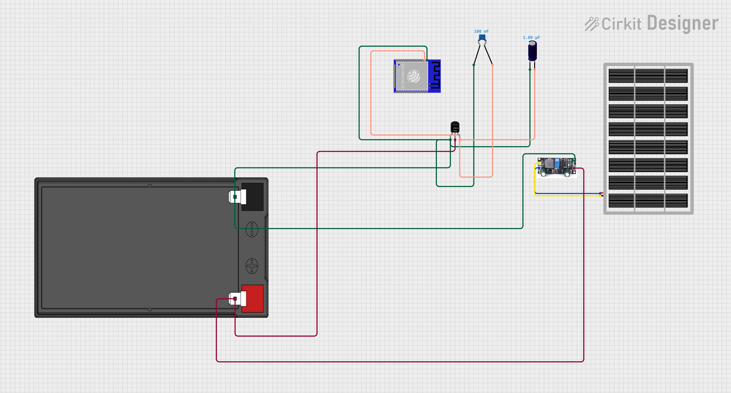
This circuit is designed to power an ESP-WROOM-32 [ESP-32S] Module using a solar panel. The solar panel charges a 12v 7ah battery through a charge controller. The battery's voltage is then regulated to a stable output voltage suitable for the ESP32 module by a voltage regulator. Ceramic and electrolytic capacitors are used for filtering and stabilizing the power supply to the ESP32 module.
Component List
Solar Panel
- Description: A photovoltaic panel that converts sunlight into electrical energy.
- Pins:
gnd,vcc
Charge Controller
- Description: Manages the power coming from the solar panel and charges the battery.
- Pins:
GND,BAT,Vin
12v 7ah Battery
- Description: A rechargeable battery that stores electrical energy.
- Pins:
12v +,12v -
Voltage Regulator
- Description: Regulates the input voltage to a steady output voltage.
- Pins:
GND,IN,OUT
Ceramic Capacitor
- Description: A capacitor used for filtering and stabilizing the voltage supply.
- Pins:
pin0,pin1 - Properties: Capacitance: 0.1 µF (microfarads)
ESP-WROOM-32 [ESP-32S] Module
- Description: A powerful Wi-Fi and Bluetooth MCU module for a wide range of applications.
- Pins:
GND,3V3,EN,SVP,SVN,IO34,IO35,IO32,IO33,IO25,IO26,IO27,IO14,IO12,IO13,SD2,SD3,RST,CLK,SD0,SD1,IO15,IO2,IO0,IO4,IO16,IO17,IO5,IO18,IO19,IO20,IO21,RXD0,TXD0,IO22,IO23
Electrolytic Capacitor
- Description: A polarized capacitor with a larger capacitance than ceramic capacitors.
- Pins:
-,+ - Properties: Capacitance: 1 µF (microfarads)
Wiring Details
Solar Panel
gndconnected to Charge ControllerGNDvccconnected to Charge ControllerBAT
Charge Controller
GNDconnected to Solar Panelgnd, Battery12v -, Voltage RegulatorGND, Ceramic Capacitorpin0, Electrolytic Capacitor-, and ESP-WROOM-32GNDBATconnected to Solar PanelvccVinconnected to Battery12v +and Voltage RegulatorIN
12v 7ah Battery
12v +connected to Charge ControllerVinand Voltage RegulatorIN12v -connected to Charge ControllerGND, Ceramic Capacitorpin0, Electrolytic Capacitor-, and ESP-WROOM-32GND
Voltage Regulator
GNDconnected to Charge ControllerGND, Ceramic Capacitorpin0, Electrolytic Capacitor-, and ESP-WROOM-32GNDINconnected to Battery12v +and Charge ControllerVinOUTconnected to Ceramic Capacitorpin1, Electrolytic Capacitor+, and ESP-WROOM-323V3
Ceramic Capacitor
pin0connected to Battery12v -, Charge ControllerGND, Voltage RegulatorGND, Electrolytic Capacitor-, and ESP-WROOM-32GNDpin1connected to Voltage RegulatorOUT, Electrolytic Capacitor+, and ESP-WROOM-323V3
ESP-WROOM-32 [ESP-32S] Module
GNDconnected to Charge ControllerGND, Battery12v -, Voltage RegulatorGND, Ceramic Capacitorpin0, and Electrolytic Capacitor-3V3connected to Voltage RegulatorOUT, Ceramic Capacitorpin1, and Electrolytic Capacitor+
Electrolytic Capacitor
-connected to Battery12v -, Charge ControllerGND, Voltage RegulatorGND, Ceramic Capacitorpin0, and ESP-WROOM-32GND+connected to Voltage RegulatorOUT, Ceramic Capacitorpin1, and ESP-WROOM-323V3
Documented Code
No code has been provided for the ESP-WROOM-32 [ESP-32S] Module. The module can be programmed using various development environments such as the Arduino IDE or the Espressif IoT Development Framework (ESP-IDF). The code would typically initialize the Wi-Fi and Bluetooth functionalities, set up GPIO pins, and handle the logic for the application the module is being used for. Without specific code, we cannot document further in this section.