
Circuit Documentation
Summary
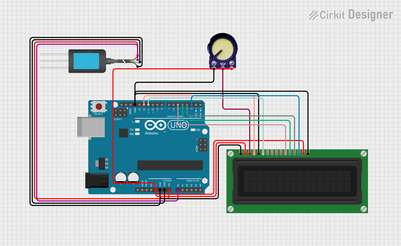
This circuit is designed to interface an Arduino UNO with an LCD display and an NPK soil sensor, with a potentiometer used to adjust the contrast of the LCD. The Arduino UNO reads the analog value from the NPK soil sensor and displays the reading on the LCD. The circuit is powered by the Arduino's 5V output, which also powers the LCD and the potentiometer. Ground connections are shared among all components.
Component List
Arduino UNO
- Microcontroller board based on the ATmega328P
- It has 14 digital input/output pins, 6 analog inputs, a 16 MHz quartz crystal, a USB connection, a power jack, an ICSP header, and a reset button.
LCD Display (16 pin)
- A 16x2 character LCD display that can show up to 32 characters on two lines.
- It has 16 pins for interfacing with a microcontroller, including pins for data, control, power, and backlight.
NPK Soil Sensor
- A sensor used to measure the nitrogen, phosphorus, and potassium content in the soil.
- It has pins for power, ground, and analog output.
Potentiometer
- A three-terminal resistor with a rotating or sliding contact that forms an adjustable voltage divider.
- It is used in this circuit to adjust the contrast of the LCD display.
Wiring Details
Arduino UNO
- 5V supplies power to the LCD display (VDD and A pins) and the potentiometer (VCC pin).
- GND is connected to the NPK Soil Sensor (GND pin), LCD Display (VSS and K pins), and Potentiometer (GND pin).
- Vin is connected to the NPK Soil Sensor (12V DC pin) for power.
- A0 is connected to the NPK Soil Sensor (A pin) to read the analog sensor value.
- D12 is connected to the LCD Display (RS pin) for register select.
- D11 is connected to the LCD Display (E pin) for enabling the display.
- D5, D4, D3, D2 are connected to the LCD Display (DB4, DB5, DB6, DB7 pins) for data transfer.
LCD Display (16 pin)
- VDD and A are powered by the Arduino's 5V output.
- VSS and K are connected to the Arduino's GND.
- RS is controlled by Arduino's D12 pin.
- R_W is connected to GND (write mode).
- E is controlled by Arduino's D11 pin.
- DB4, DB5, DB6, DB7 are connected to Arduino's D5, D4, D3, D2 pins respectively for 4-bit data mode.
- VO is connected to the wiper (output) of the potentiometer to adjust the contrast.
NPK Soil Sensor
- 12V DC is powered by the Arduino's Vin.
- A is connected to the Arduino's A0 pin for analog output.
- GND is connected to the Arduino's GND.
Potentiometer
- VCC is connected to the Arduino's 5V output.
- Output is connected to the LCD's VO pin for contrast control.
- GND is connected to the Arduino's GND.
Documented Code
#include <LiquidCrystal.h>

// Initialize the library with the numbers of the interface pins
LiquidCrystal lcd(12, 11, 5, 4, 3, 2);

void setup() {
  // Set up the LCD's number of columns and rows:
  lcd.begin(16, 2);
  // Print a message to the LCD.
  lcd.print("NPK Sensor");
  // Initialize serial communication at 9600 bits per second:
  Serial.begin(9600);
}

void loop() {
  // Read the NPK sensor value
  int sensorValue = analogRead(A0);

  // Print the sensor value to the serial monitor
  Serial.print("NPK Sensor Value: ");
  Serial.println(sensorValue);

  // Display the sensor value on the LCD
  lcd.setCursor(0, 1); // Move to the second line
  lcd.print("NPK: ");
  lcd.print(sensorValue);
  lcd.print("    "); // Clear any previous value

  delay(1000); // Wait for a second before the next loop
}
This code is designed to run on the Arduino UNO. It initializes the LCD display and sets up serial communication. In the main loop, it reads the analog value from the NPK sensor and displays it on both the serial monitor and the LCD. The LCD displays the text "NPK Sensor" on the first line and the sensor value prefixed with "NPK: " on the second line. The sensor value is updated every second.