ESP32-Based Multi-Sensor Robotic Controller with Dual L298N Motor Drivers

Circuit Documentation
Summary
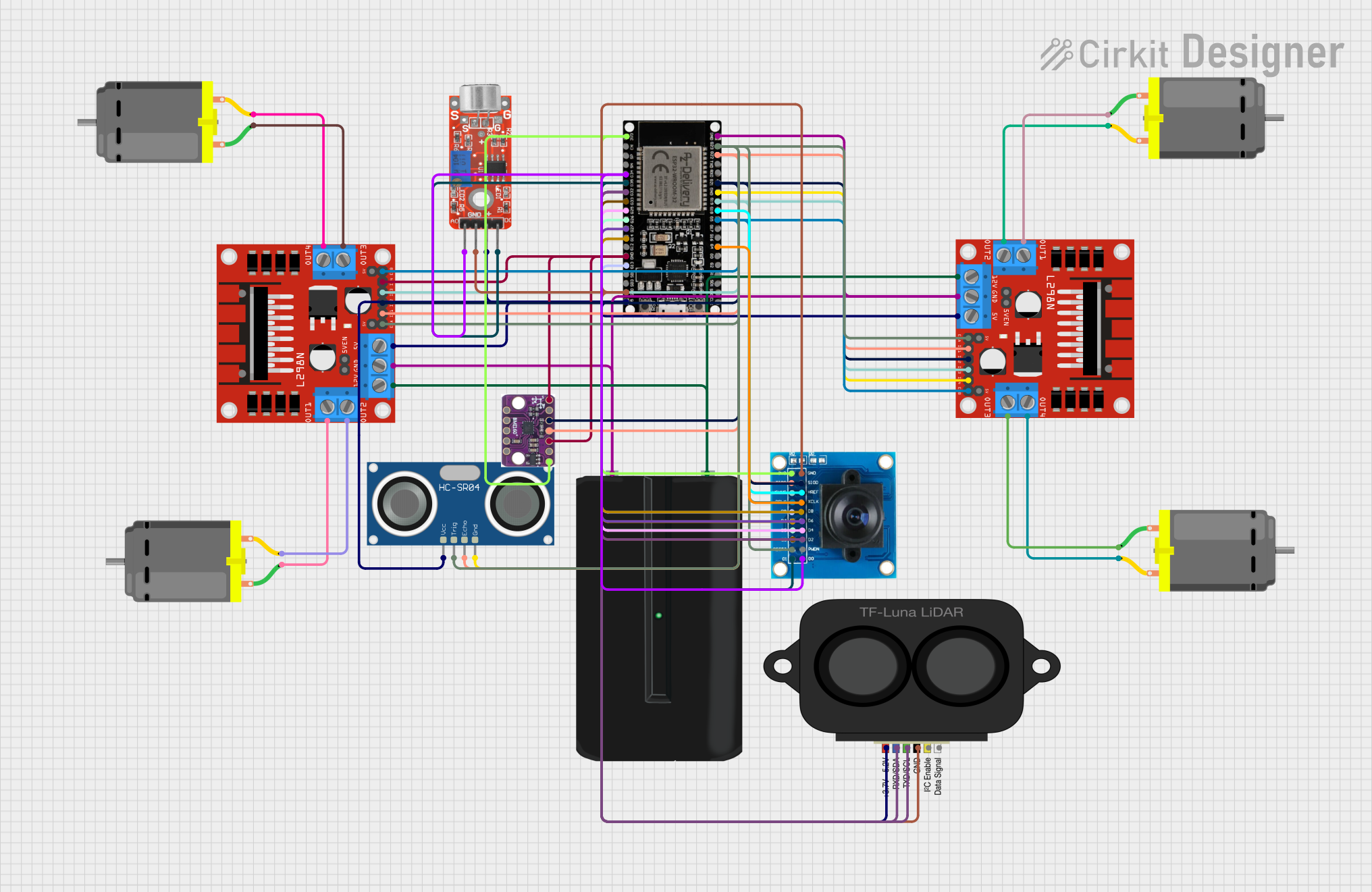
The circuit in question appears to be a complex system designed to control multiple DC motors, interface with various sensors, and process image data. The central processing unit of the circuit is an ESP32 microcontroller, which is responsible for handling inputs and outputs, as well as running the embedded code. The circuit includes motor drivers for controlling DC motors, a battery for power supply, and a variety of sensors including an ultrasonic sensor, a camera module, a microphone, a LIDAR sensor, and an accelerometer/gyro sensor. The circuit is likely intended for a robotics application, given the presence of motion control components and various sensors for environmental interaction.
Component List
ESP32 38 PINS
- Microcontroller with WiFi and Bluetooth capabilities.
- 38 GPIO pins including digital, analog, and power pins.
L298N DC Motor Driver (x2)
- Dual H-bridge motor driver capable of driving two DC motors each.
- Provides motor speed and direction control.
NPF570 Battery
- Power source for the circuit.
DC Motor (x4)
- Actuators for providing motion to the system.
OV7725
- Camera module for capturing image data.
HC-SR04 Ultrasonic Sensor
- Sensor for measuring distance via ultrasonic waves.
KY-037 Microphone
- Sound detection sensor with both analog and digital outputs.
TF LUNA LIDAR
- Distance measurement sensor using LIDAR technology.
BMI160 Accelerometer Gyro - 6DOF Sensor
- Inertial measurement unit (IMU) providing 6 degrees of freedom.
Wiring Details
ESP32 38 PINS
- GND connected to the ground of the battery, motor drivers, ultrasonic sensor, camera module, microphone, and LIDAR sensor.
- G23 controls ENA pins on both motor drivers.
- G22 connected to ECHO pin of ultrasonic sensor and SIOC pin of camera module.
- G21 connected to IN2 pins on both motor drivers and SIOD pin of camera module.
- G19 controls IN3 pins on both motor drivers and connected to VSYNC pin of camera module.
- G18 connected to HREF pin of camera module.
- G5 controls ENB pins on both motor drivers and connected to PCLK pin of camera module.
- G4 connected to XCLK pin of camera module.
- 3V3 supplies power to the accelerometer/gyro sensor and 3V3 pin of camera module.
- G34 connected to the analog output of the microphone and D0 pin of camera module.
- G35 connected to the digital output of the microphone and D1 pin of camera module.
- G32 controls RXD/SDA and TXD/SCL pins of LIDAR sensor and connected to D2 pin of camera module.
- 33 connected to D3 pin of camera module.
- G25 connected to D4 pin of camera module.
- G26 connected to D5 pin of camera module.
- G27 connected to D6 pin of camera module.
- G14 connected to D7, D8 pins of camera module.
- G13 connected to D9 pin of camera module.
- 5V supplies power to the motor drivers, ultrasonic sensor, microphone, and LIDAR sensor.
L298N DC Motor Driver (Instance 1)
- GND connected to the ground of the battery.
- ENA controlled by ESP32 pin G23.
- IN1 controlled by ESP32 pin G22.
- IN2 controlled by ESP32 pin G21.
- IN3 controlled by ESP32 pin G19.
- ENB controlled by ESP32 pin G5.
- 12V connected to the positive terminal of the battery.
- OUT1 and OUT2 connected to DC Motor (Instance 1).
L298N DC Motor Driver (Instance 2)
- GND connected to the ground of the battery.
- ENA controlled by ESP32 pin G23.
- IN1 controlled by ESP32 pin G22.
- IN2 controlled by ESP32 pin G21.
- IN3 controlled by ESP32 pin G19.
- IN4 controlled by ESP32 pin GND.
- ENB controlled by ESP32 pin G5.
- 12V connected to the positive terminal of the battery.
- OUT1 and OUT2 connected to DC Motor (Instance 2).
- OUT3 and OUT4 connected to DC Motor (Instance 3 and 4 respectively).
NPF570 Battery
- "+" connected to 12V pins of both motor drivers.
- "-" connected to GND pins of both motor drivers and ESP32.
DC Motor (Instance 1)
- Pin 1 connected to OUT1 of Motor Driver (Instance 1).
- Pin 2 connected to OUT2 of Motor Driver (Instance 1).
DC Motor (Instance 2)
- Pin 1 connected to OUT3 of Motor Driver (Instance 1).
- Pin 2 connected to OUT4 of Motor Driver (Instance 1).
DC Motor (Instance 3)
- Pin 1 connected to OUT1 of Motor Driver (Instance 2).
- Pin 2 connected to OUT2 of Motor Driver (Instance 2).
DC Motor (Instance 4)
- Pin 1 connected to OUT3 of Motor Driver (Instance 2).
- Pin 2 connected to OUT4 of Motor Driver (Instance 2).
OV7725
- 3V3 and GND connected to ESP32 for power.
- SIOC, SIOD, VSYNC, HREF, PCLK, XCLK, D0 to D9 connected to corresponding GPIO pins on ESP32.
HC-SR04 Ultrasonic Sensor
- VCC connected to 5V on ESP32.
- TRIG controlled by ESP32 pin G23.
- ECHO connected to ESP32 pin G22.
- GND connected to ESP32 ground.
KY-037 Microphone
- Analog output connected to ESP32 pin G34.
- Digital output connected to ESP32 pin G35.
- Ground connected to ESP32 ground.
- VCC connected to 5V on ESP32.
TF LUNA LIDAR
- Power connected to 5V on ESP32.
- RXD/SDA and TXD/SCL controlled by ESP32 pin G32.
- GND connected to ESP32 ground.
BMI160 Accelerometer Gyro - 6DOF Sensor
- VIN connected to 3V3 on ESP32.
- SCL and SDA connected to corresponding I2C pins on ESP32.
- GND connected to ESP32 ground.
Documented Code
No code was provided for the microcontrollers in the circuit. Therefore, this section is left blank until the relevant code is supplied. The code would typically include initialization routines for the sensors and motor drivers, as well as the main control loop for processing sensor data and controlling the motors based on the application's requirements.