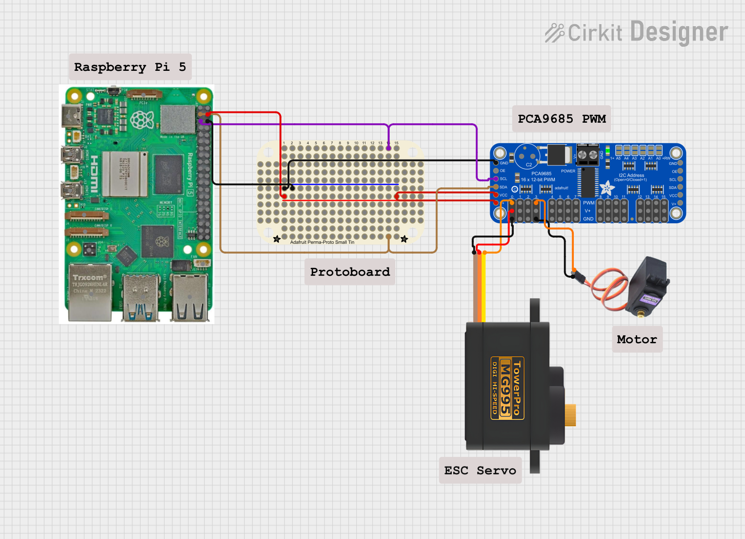
Raspberry Pi-Controlled Dual Servo Driver with PCA9685 Interface

Circuit Documentation
Summary of the Circuit
This circuit appears to be designed to control servomotors using a Raspberry Pi 5 and an Adafruit PCA9685 PWM Servo Breakout board. The Adafruit Perma Proto Small Mint board is likely used as a prototyping platform to facilitate connections between the Raspberry Pi, the PCA9685 breakout board, and the servomotors. The servomotors in the circuit are the MG996R and the MG995, which are commonly used for tasks requiring robust and precise positioning.
Component List
Adafruit Perma Proto Small Mint
- Description: A small prototyping board used for creating permanent circuit designs.
- Purpose: To provide a platform for making connections between the Raspberry Pi, the PCA9685 breakout board, and the servomotors.
Adafruit PCA9685 PWM Servo Breakout
- Description: A 16-channel, 12-bit PWM breakout board capable of controlling multiple servomotors.
- Purpose: To generate PWM signals for controlling the servomotors connected to it.
MG996R Servomotor
- Description: A high-torque digital servomotor.
- Purpose: To perform mechanical actions as instructed by the PWM signals.
Servomotor MG995
- Description: Another high-torque digital servomotor similar to the MG996R.
- Purpose: To perform mechanical actions as instructed by the PWM signals.
Raspberry Pi 5
- Description: A small single-board computer with a variety of I/O options.
- Purpose: To serve as the main controller of the circuit, sending commands to the PCA9685 breakout board.
Comments
- Description: Placeholder components that may represent annotations or notes in the circuit design.
Wiring Details
Adafruit Perma Proto Small Mint
- Connections:
PWRconnected to Raspberry Pi 55Vand Adafruit PCA96855.0VandVCC.GNDconnected to Raspberry Pi 5GNDand Adafruit PCA9685GND.Nconnected to Raspberry Pi 5GPIO 2(SDA).Qconnected to Raspberry Pi 5GPIO 3(SCL).
Adafruit PCA9685 PWM Servo Breakout
- Connections:
PWM3connected to MG996RSIG.PWM0connected to Servomotor MG995SIG.GNDconnected to MG996RGNDand Servomotor MG995GND.5.0Vconnected to Servomotor MG995VCC.SDAconnected to Raspberry Pi 5GPIO 2.SCLconnected to Raspberry Pi 5GPIO 3.VCCconnected to Adafruit Perma Proto Small MintPWR.
MG996R Servomotor
- Connections:
SIGconnected to Adafruit PCA9685PWM3.GNDconnected to Adafruit PCA9685GND.
Servomotor MG995
- Connections:
SIGconnected to Adafruit PCA9685PWM0.VCCconnected to Adafruit PCA96855.0V.GNDconnected to Adafruit PCA9685GND.
Raspberry Pi 5
- Connections:
GPIO 2(SDA) connected to Adafruit PCA9685SDAand Adafruit Perma Proto Small MintN.GPIO 3(SCL) connected to Adafruit PCA9685SCLand Adafruit Perma Proto Small MintQ.5Vconnected to Adafruit Perma Proto Small MintPWR.GNDconnected to Adafruit Perma Proto Small MintGND.
Documented Code
No code has been provided for the microcontrollers in the circuit. Typically, the Raspberry Pi would run a Python script or another program to communicate with the PCA9685 breakout board via the I2C interface, sending commands to control the servomotors. Without the code, we cannot document the specific functionality or behavior of the system.