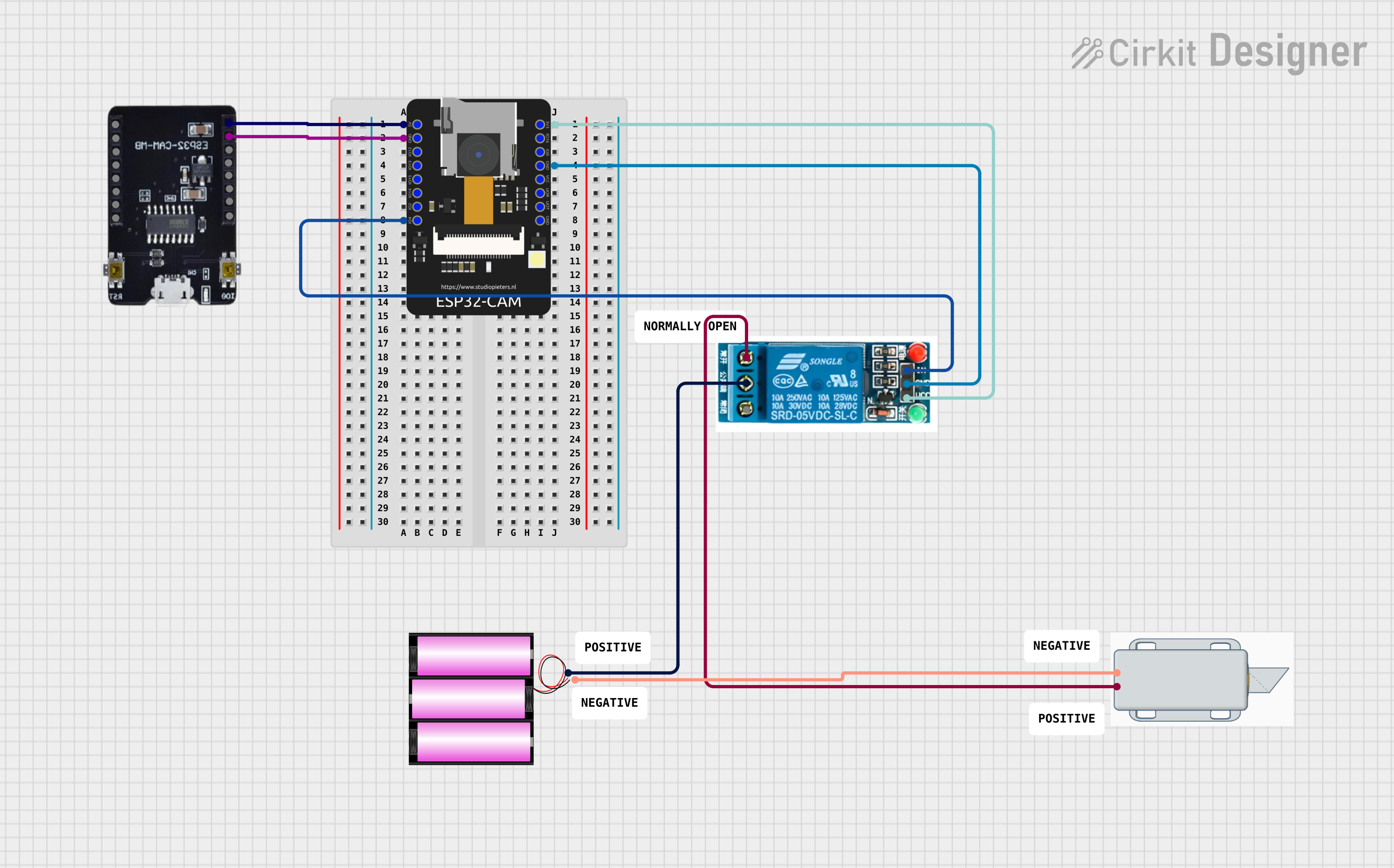
ESP32-CAM Controlled Wi-Fi Smart Lock

Circuit Documentation
Summary
The circuit in question appears to be designed for a security or access control application, utilizing an ESP32-CAM module to potentially capture images or video. The ESP32-CAM is interfaced with a 5V relay that controls a 12V solenoid lock, allowing for electronic locking and unlocking mechanisms. The system is powered by a 12V battery, and the ESP32-CAM module is mounted on an ESP32-CAM MB FLIP for ease of use. The embedded code provided suggests that the ESP32-CAM is configured for WiFi connectivity and may perform facial recognition or similar image processing tasks to control the relay and, consequently, the solenoid lock.
Component List
ESP32-CAM
- Description: A small-sized ESP32-based module with WiFi and camera capabilities.
- Pins: 5V, GND, IO12, IO13, IO15, IO14, IO2, IO4, VOT, VOR, VCC, IO0, IO16, 3V3
12V Solenoid Lock
- Description: An electromechanical lock that can be controlled electronically, typically used in access control systems.
- Pins: -, +
Battery 12V
- Description: A 12V battery providing power to the circuit.
- Pins: +, -
5V Relay
- Description: An electromechanical switch that allows a low-power circuit to switch a relatively high current or voltage on and off.
- Pins: Normally Open, Common terminal, Normally Closed, In, GND, VCC
ESP32-CAM MB FLIP
- Description: A breakout board for the ESP32-CAM module, providing easier access to the module's pins and additional functionality.
- Pins: 3.3V, IO16, IO0, GND, VCC, IO3RX, IO1TX, 5V, IO12, IO13, IO15, IO14, IO2, IO4
Comments
- Description: Placeholder components for additional notes or documentation within the circuit design.
Wiring Details
ESP32-CAM
- 5V connected to ESP32-CAM MB FLIP 5V
- 3V3 connected to 5V Relay VCC
- GND connected to ESP32-CAM MB FLIP GND and 5V Relay GND
- IO4 connected to 5V Relay In
12V Solenoid Lock
- - connected to Battery 12V -
- + connected to 5V Relay Normally Open
Battery 12V
- + connected to 5V Relay Common terminal
- - connected to 12V Solenoid Lock -
5V Relay
- VCC connected to ESP32-CAM 3V3
- GND connected to ESP32-CAM GND
- In connected to ESP32-CAM IO4
- Normally Open connected to 12V Solenoid Lock +
- Common terminal connected to Battery 12V +
Documented Code
#include "esp_camera.h"
#include <WiFi.h>

// WARNING!!! PSRAM enabled board is required for this camera module type
#define CAMERA_MODEL_AI_THINKER
#include "camera_pins.h"

const char* ssid = "Galaxy-M20";
const char* password = "ac312124";

#define LED_BUILTIN 4
#define relay 4
#define buzzer 2

boolean matchFace = false;
boolean activeRelay = false;
long prevMillis = 0;
int interval = 5000;

void startCameraServer();

void setup() {
  Serial.begin(115200);
  Serial.setDebugOutput(true);
  Serial.println();

  pinMode(relay, OUTPUT);
  pinMode(buzzer, OUTPUT);
  pinMode (LED_BUILTIN, OUTPUT);

  digitalWrite(LED_BUILTIN, LOW);
  digitalWrite(relay, LOW);
  digitalWrite(buzzer, LOW);

  // Camera configuration
  camera_config_t config;
  config.ledc_channel = LEDC_CHANNEL_0;
  config.ledc_timer = LEDC_TIMER_0;
  // ... (omitted for brevity)
  // Camera initialization
  esp_err_t err = esp_camera_init(&config);
  if (err != ESP_OK) {
    Serial.printf("Camera init failed with error 0x%x", err);
    return;
  }

  // Connect to WiFi
  WiFi.begin(ssid, password);
  while (WiFi.status() != WL_CONNECTED) {
    delay(500);
    Serial.print(".");
  }
  Serial.println("WiFi connected");
  startCameraServer();
  Serial.print("Camera Ready! Use 'http://");
  Serial.print(WiFi.localIP());
  Serial.println("' to connect");
}

void loop() {
  if (matchFace == true && activeRelay == false){
    activeRelay = true;
    digitalWrite (relay, HIGH);
    digitalWrite (buzzer, HIGH);
    delay(800);
    digitalWrite (buzzer, LOW);
    prevMillis = millis();
  }
  if(activeRelay == true && millis()- prevMillis > interval){
    activeRelay = false;
    matchFace = false;
    digitalWrite(relay, LOW);
  }
}
Note: The code provided is for the ESP32-CAM microcontroller and includes setup for the camera, WiFi connectivity, and control logic for a relay and buzzer based on facial recognition or other triggering conditions. The actual facial recognition logic is not included in the provided code snippet.