
Circuit Documentation
Summary
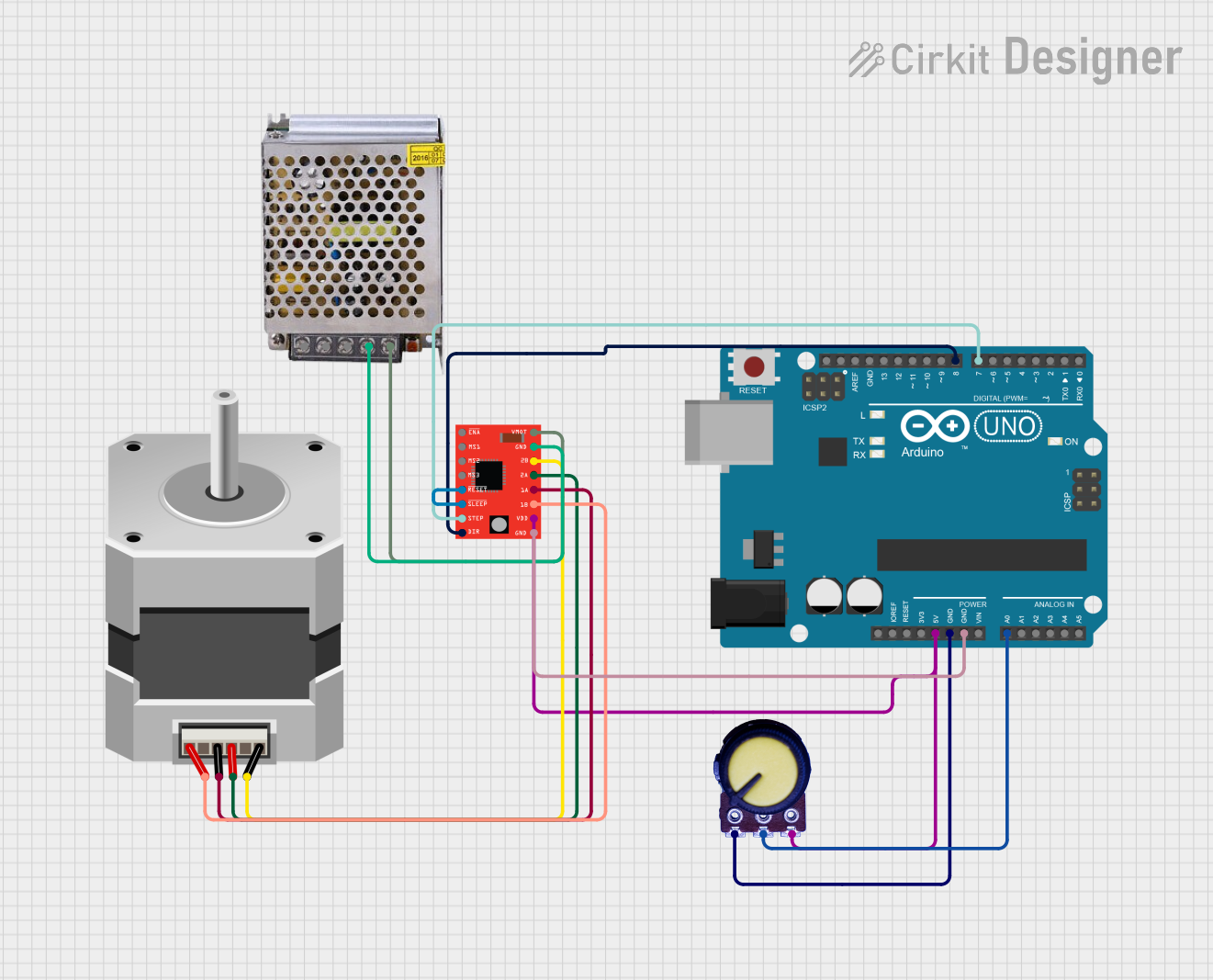
This circuit is designed to control a bipolar stepper motor using an A4988 stepper motor driver. The Arduino UNO serves as the main controller, interfacing with a potentiometer for adjustable control parameters and sending signals to the A4988 driver, which in turn drives the stepper motor. The power supply provides the necessary voltage to the motor driver and the motor.
Component List
Stepper Motor (Bipolar)
- Description: A bipolar stepper motor which requires a driver to control its two coils.
- Pins: D, B, C, A
Arduino UNO
- Description: A microcontroller board based on the ATmega328P, used for controlling the logic of the circuit.
- Pins: UNUSED, IOREF, Reset, 3.3V, 5V, GND, Vin, A0-A5, SCL, SDA, AREF, D0-D13
Potentiometer
- Description: A variable resistor with three terminals, used to provide an adjustable voltage.
- Pins: GND, Output, VCC
A4988 Stepper Motor Driver (Red)
- Description: A compact driver for controlling stepper motors via digital signals.
- Pins: ENABLE, MS1, MS2, MS3, RESET, SLEEP, STEP, DIR, VMOT, GND, 2B, 2A, 1A, 1B, VDD
POWER SUPPLY 12V 5AMP
- Description: A power supply unit that provides 12V DC output from a 220V AC input.
- Pins: 220V Positive Pole (AC), 220V Negative Pole (AC), GND, GND (DC), 12V-24V Output (DC)
Wiring Details
Stepper Motor (Bipolar)
- D: Connected to A4988 Driver 2B
- B: Connected to A4988 Driver 2A
- C: Connected to A4988 Driver 1A
- A: Connected to A4988 Driver 1B
Arduino UNO
- 5V: Connected to Potentiometer VCC and A4988 Driver VDD
- GND: Common ground with Potentiometer and A4988 Driver
- A0: Connected to Potentiometer Output
- D8: Connected to A4988 Driver DIR
- D7: Connected to A4988 Driver STEP
Potentiometer
- GND: Connected to Arduino UNO GND
- Output: Connected to Arduino UNO A0
- VCC: Connected to Arduino UNO 5V
A4988 Stepper Motor Driver (Red)
- 2B: Connected to Stepper Motor D
- 2A: Connected to Stepper Motor B
- 1A: Connected to Stepper Motor C
- 1B: Connected to Stepper Motor A
- VDD: Connected to Arduino UNO 5V and Potentiometer VCC
- GND: Common ground with Arduino UNO and Power Supply GND (DC)
- DIR: Connected to Arduino UNO D8
- STEP: Connected to Arduino UNO D7
- RESET: Shorted to SLEEP
- SLEEP: Shorted to RESET
- VMOT: Connected to Power Supply 12V-24V Output (DC)
POWER SUPPLY 12V 5AMP
- 12V-24V Output (DC): Connected to A4988 Driver VMOT
- GND (DC): Connected to A4988 Driver GND
Documented Code
Arduino UNO Code (sketch.ino)
void setup() {
  // put your setup code here, to run once:

}

void loop() {
  // put your main code here, to run repeatedly:

}
Additional Notes
- The provided code is a template and does not contain any functional implementation for controlling the stepper motor. The setup and loop functions need to be populated with the appropriate code to initialize the motor driver and to control the motor based on the input from the potentiometer.
- The
documentation.txtfile is empty and does not provide additional information. Further documentation should be added to describe the functionality and the operation of the code once implemented.