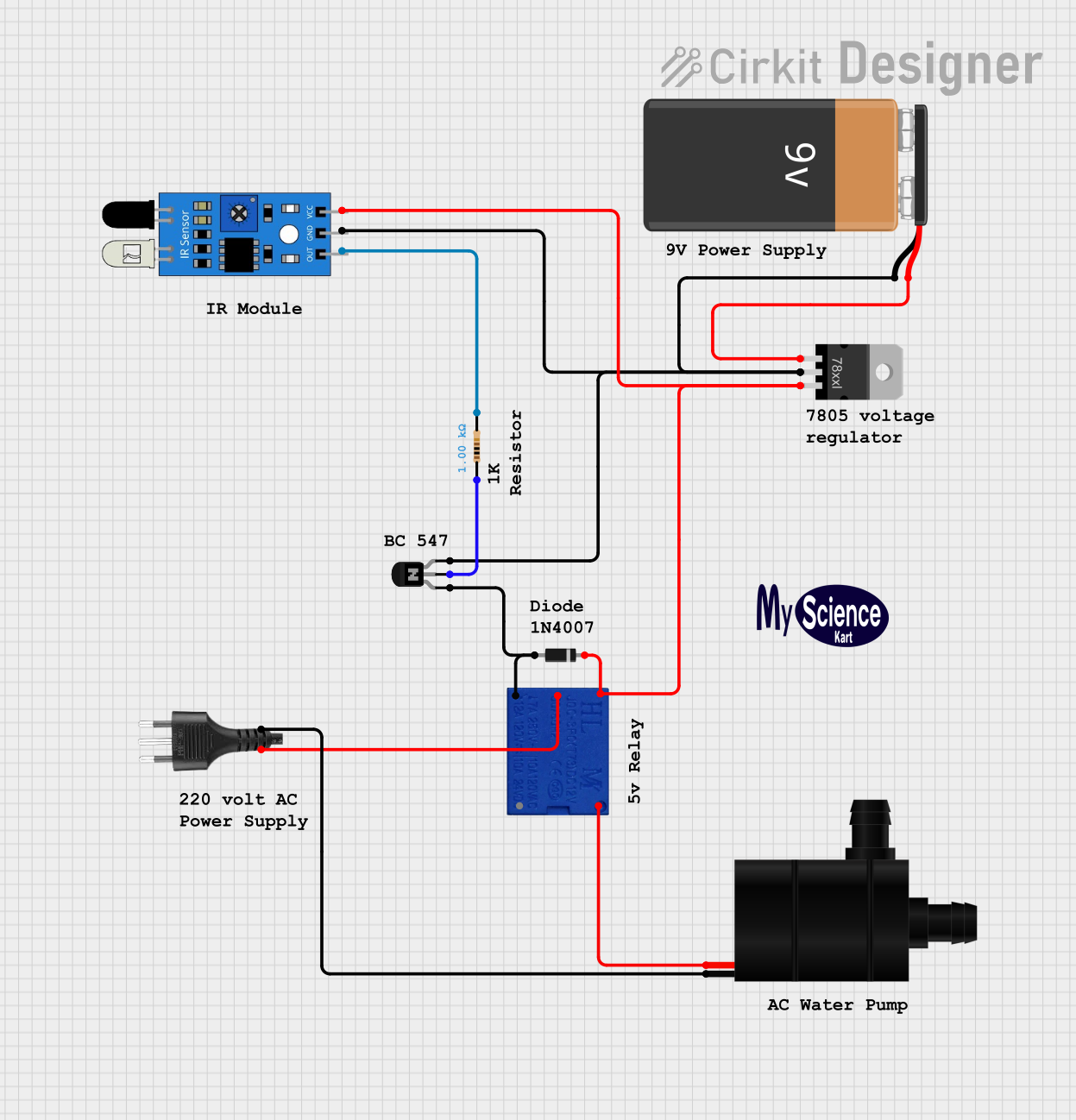
IR Sensor-Activated Water Pump with Relay Control

Circuit Documentation
Summary
The circuit described by the provided inputs is a control circuit that utilizes a relay to switch a water pump on and off based on the output of an IR sensor. The circuit includes a voltage regulator to step down the voltage from a 9V battery to a lower voltage suitable for the relay coil and the IR sensor. A diode is used for flyback protection when the relay is de-energized. An NPN transistor is used to amplify the IR sensor output to drive the relay coil. A resistor is included to limit the base current of the transistor. The water pump is powered directly by the relay contacts, and the socket provides a connection point for the pump.
Component List
- Relay 5V: A relay with a 5V coil voltage used to switch the water pump on and off.
- Resistor: A 1000 Ohm resistor used to limit the base current of the NPN transistor.
- Voltage Regulator: A component that steps down the voltage from the 9V battery to a lower voltage suitable for the relay coil and the IR sensor.
- NPN Transistor (EBC): A bipolar junction transistor used to amplify the IR sensor output to drive the relay coil.
- Diode: A diode used for flyback protection when the relay is de-energized.
- 9V Battery: The power source for the circuit.
- Socket: A connection point for the water pump.
- Water Pump: The load to be switched by the relay.
- IR Sensor: A sensor that detects the presence of an object and controls the relay accordingly.
Wiring Details
Relay 5V
- COM: Connected to the positive terminal of the socket.
- COIL 1: Connected to the emitter of the NPN transistor and the anode of the diode.
- COIL 2: Connected to the IR sensor VCC, the cathode of the diode, and the output of the voltage regulator.
- NO: Connected to the VCC of the water pump.
- NC: Not connected.
Resistor
- Pin1: Connected to the base of the NPN transistor.
- Pin2: Connected to the output of the IR sensor.
Voltage Regulator
- IN: Connected to the positive terminal of the 9V battery.
- GND: Connected to the negative terminal of the 9V battery, the collector of the NPN transistor, and the GND of the IR sensor.
- OUT: Connected to the COIL 2 of the relay 5V.
NPN Transistor (EBC)
- Emitter: Connected to COIL 1 of the relay 5V.
- Base: Connected to Pin1 of the resistor.
- Collector: Connected to the negative terminal of the 9V battery.
Diode
- Cathode: Connected to COIL 2 of the relay 5V.
- Anode: Connected to COIL 1 of the relay 5V.
9V Battery
- +: Connected to the IN of the voltage regulator.
- -: Connected to the GND of the voltage regulator.
Socket
- Positive: Connected to the COM of the relay 5V.
- Negative: Connected to the GND of the water pump.
Water Pump
- VCC: Connected to the NO of the relay 5V.
- GND: Connected to the negative terminal of the socket.
IR Sensor
- VCC: Connected to COIL 2 of the relay 5V.
- GND: Connected to the GND of the voltage regulator.
- Out: Connected to Pin2 of the resistor.
Documented Code
No code has been provided for any microcontrollers in the circuit. If the circuit includes a microcontroller, please provide the relevant code for documentation.