
Arduino UNO Light Sensor with LDR for Ambient Light Detection
View and Edit Project In Cirkit Designer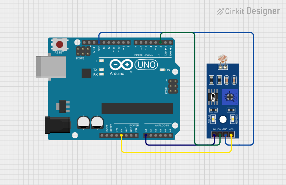
Circuit Documentation
Summary
This circuit consists of an Arduino UNO microcontroller and an LDR (Light Dependent Resistor) sensor. The LDR is used to detect light intensity, and the Arduino UNO processes the sensor data. The circuit is powered by the 5V output from the Arduino UNO.
Component List
Arduino UNO
- Description: A microcontroller board based on the ATmega328P.
- Pins: UNUSED, IOREF, Reset, 3.3V, 5V, GND, Vin, A0, A1, A2, A3, A4, A5, SCL, SDA, AREF, D13, D12, D11, D10, D9, D8, D7, D6, D5, D4, D3, D2, D1, D0
- Purpose in Circuit: Acts as the main controller, processing data from the LDR sensor.
LDR (Light Dependent Resistor)
- Description: A sensor that changes its resistance based on the light intensity.
- Pins: A0, D0, GND, VCC
- Purpose in Circuit: Measures the light intensity and sends the data to the Arduino UNO.
Wiring Details
Arduino UNO
- 5V: Connected to VCC of the LDR.
- A0: Connected to A0 of the LDR.
- GND: Connected to GND of the LDR.
- D2: Connected to D0 of the LDR.
LDR
- VCC: Connected to 5V of the Arduino UNO.
- A0: Connected to A0 of the Arduino UNO.
- GND: Connected to GND of the Arduino UNO.
- D0: Connected to D2 of the Arduino UNO.
Code Documentation
Arduino UNO Code
void setup() {
  // put your setup code here, to run once:

}

void loop() {
  // put your main code here, to run repeatedly:

}
This code is a basic template for the Arduino UNO. The setup() function is where you initialize your settings, and the loop() function is where the main code runs repeatedly. You can add your specific logic to read the LDR sensor data and process it accordingly.
This documentation provides a comprehensive overview of the circuit, including the components used, their wiring details, and the initial code setup for the Arduino UNO.