
Circuit Documentation
Summary
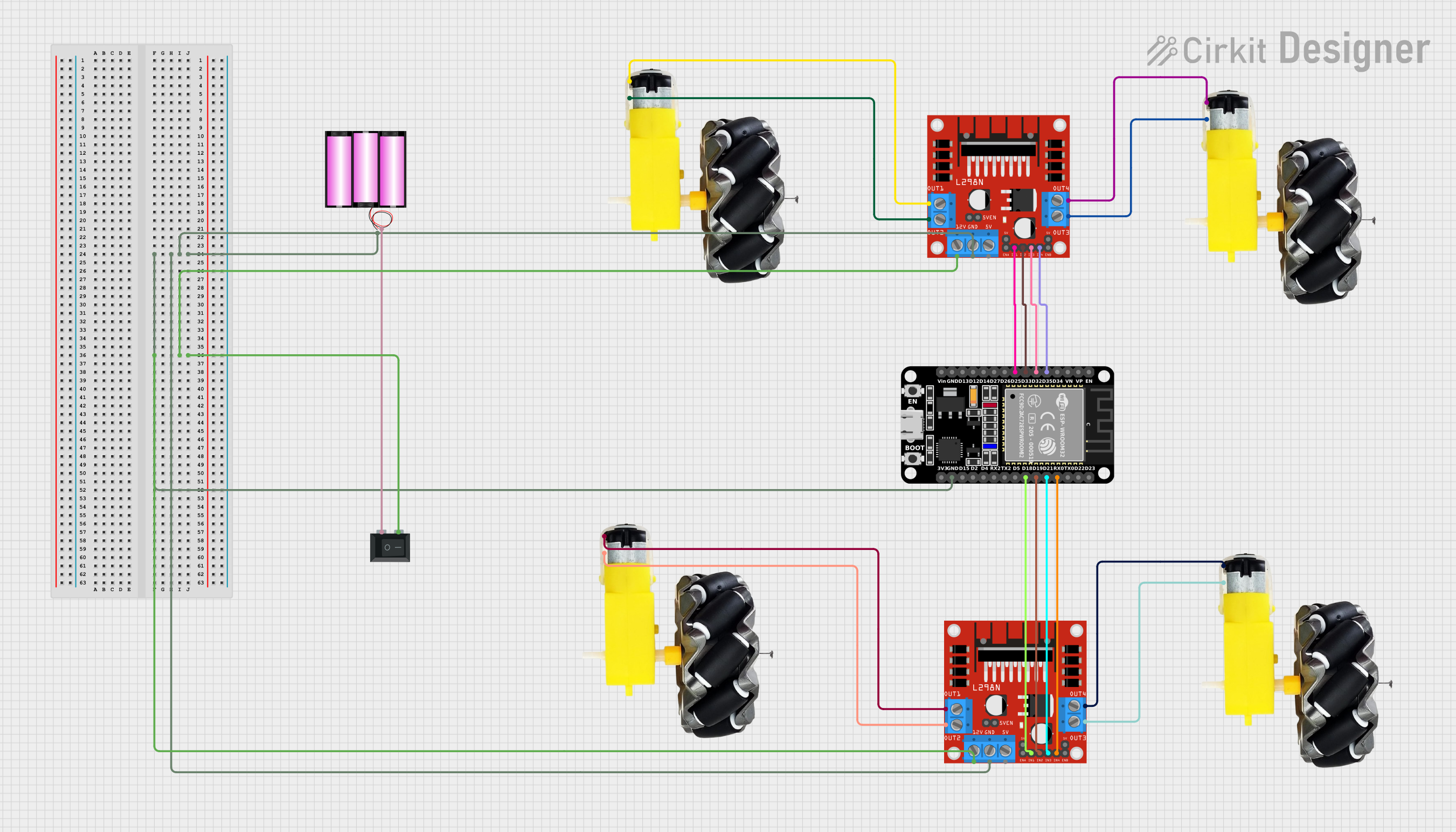
This document provides a detailed overview of a circuit designed to control a set of DC motors using an ESP32 microcontroller and L298N motor drivers. The circuit includes a 12V battery for power, a rocker switch for power control, and multiple motor and wheel assemblies. The ESP32 is programmed to control the motors via a web interface, allowing for remote operation.
Component List
ESP32 (30 pin)
- Description: A powerful microcontroller with built-in Wi-Fi and Bluetooth capabilities.
- Pins: EN, VP, VN, D34, D35, D32, D33, D25, D26, D27, D14, D12, D13, GND, Vin, D23, D22, TX0, RX0, D21, D19, D18, D5, TX2, RX2, D4, D2, D15, 3V3
L298N DC Motor Driver
- Description: A dual H-Bridge motor driver that allows for control of two DC motors.
- Pins: OUT1, OUT2, 12V, GND, 5V, OUT3, OUT4, 5V-ENA-JMP-I, 5V-ENA-JMP-O, +5V-J1, +5V-J2, ENA, IN1, IN2, IN3, IN4, ENB
Motor and Wheels
- Description: A DC motor with attached wheels for movement.
- Pins: vcc, GND
Battery 12V
- Description: A 12V battery used to power the circuit.
- Pins: +, -
Rocker Switch (SPST)
- Description: A single-pole single-throw switch used to control the power supply.
- Pins: 1, 2
Wiring Details
ESP32 (30 pin)
- GND is connected to the GND pins of both L298N motor drivers and the negative terminal of the 12V battery.
- D35 is connected to IN4 of the second L298N motor driver.
- D32 is connected to IN3 of the second L298N motor driver.
- D33 is connected to IN2 of the second L298N motor driver.
- D25 is connected to IN1 of the second L298N motor driver.
- RX0 is connected to IN4 of the first L298N motor driver.
- D21 is connected to IN3 of the first L298N motor driver.
- D19 is connected to IN2 of the first L298N motor driver.
- D18 is connected to IN1 of the first L298N motor driver.
L298N DC Motor Driver (First)
- GND is connected to the GND pin of the ESP32 and the negative terminal of the 12V battery.
- 12V is connected to pin 2 of the rocker switch.
- IN4 is connected to RX0 of the ESP32.
- IN3 is connected to D21 of the ESP32.
- IN2 is connected to D19 of the ESP32.
- IN1 is connected to D18 of the ESP32.
- OUT1 is connected to vcc of the first motor and wheels.
- OUT2 is connected to GND of the first motor and wheels.
- OUT3 is connected to GND of the second motor and wheels.
- OUT4 is connected to vcc of the second motor and wheels.
L298N DC Motor Driver (Second)
- GND is connected to the GND pin of the ESP32 and the negative terminal of the 12V battery.
- 12V is connected to pin 2 of the rocker switch.
- IN4 is connected to D35 of the ESP32.
- IN3 is connected to D32 of the ESP32.
- IN2 is connected to D33 of the ESP32.
- IN1 is connected to D25 of the ESP32.
- OUT1 is connected to vcc of the third motor and wheels.
- OUT2 is connected to GND of the third motor and wheels.
- OUT3 is connected to GND of the fourth motor and wheels.
- OUT4 is connected to vcc of the fourth motor and wheels.
Motor and Wheels
First Motor
- vcc is connected to OUT1 of the first L298N motor driver.
- GND is connected to OUT2 of the first L298N motor driver.
Second Motor
- vcc is connected to OUT4 of the first L298N motor driver.
- GND is connected to OUT3 of the first L298N motor driver.
Third Motor
- vcc is connected to OUT1 of the second L298N motor driver.
- GND is connected to OUT2 of the second L298N motor driver.
Fourth Motor
- vcc is connected to OUT4 of the second L298N motor driver.
- GND is connected to OUT3 of the second L298N motor driver.
Battery 12V
- + is connected to pin 1 of the rocker switch.
- - is connected to the GND pins of both L298N motor drivers and the GND pin of the ESP32.
Rocker Switch (SPST)
- Pin 1 is connected to the positive terminal of the 12V battery.
- Pin 2 is connected to the 12V pins of both L298N motor drivers.
Code Documentation
#include <Arduino.h>
#ifdef ESP32
#include <WiFi.h>
#include <AsyncTCP.h>
#elif defined(ESP8266)
#include <ESP8266WiFi.h>
#include <ESPAsyncTCP.h>
#endif
#include <ESPAsyncWebServer.h>
#define UP 1
#define DOWN 2
#define LEFT 3
#define RIGHT 4
#define UP_LEFT 5
#define UP_RIGHT 6
#define DOWN_LEFT 7
#define DOWN_RIGHT 8
#define TURN_LEFT 9
#define TURN_RIGHT 10
#define STOP 0
#define FRONT_RIGHT_MOTOR 0
#define BACK_RIGHT_MOTOR 1
#define FRONT_LEFT_MOTOR 2
#define BACK_LEFT_MOTOR 3
#define FORWARD 1
#define BACKWARD -1
struct MOTOR_PINS
{
int pinIN1;
int pinIN2;
};
std::vector<MOTOR_PINS> motorPins =
{
{16, 17}, //FRONT_RIGHT_MOTOR
{18, 19}, //BACK_RIGHT_MOTOR
{27, 26}, //FRONT_LEFT_MOTOR
{25, 33}, //BACK_LEFT_MOTOR
};
const char* ssid = "Galaxy M55 5G 7277";
const char* password = "12345678910";
AsyncWebServer server(80);
AsyncWebSocket ws("/ws");
const char* htmlHomePage PROGMEM = R"HTMLHOMEPAGE(
<!DOCTYPE html>
<html>
<head>
<meta name="viewport" content="width=device-width, initial-scale=1, maximum-scale=1, user-scalable=no">
<style>
.arrows {
font-size:70px;
color:red;
}
.circularArrows {
font-size:80px;
color:blue;
}
td {
background-color:black;
border-radius:25%;
box-shadow: 5px 5px #888888;
}
td:active {
transform: translate(5px,5px);
box-shadow: none;
}
.noselect {
-webkit-touch-callout: none; /* iOS Safari */
-webkit-user-select: none; /* Safari */
-khtml-user-select: none; /* Konqueror HTML */
-moz-user-select: none; /* Firefox */
-ms-user-select: none; /* Internet Explorer/Edge */
user-select: none; /* Non-prefixed version, currently
supported by Chrome and Opera */
}
</style>
</head>
<body class="noselect" align="center" style="background-color:white">
<h1 style="color: teal;text-align:center;">Hash Include Electronics</h1>
<h2 style="color: teal;text-align:center;">Wi-Fi 🚗 Control</h2>
<table id="mainTable" style="width:400px;margin:auto;table-layout:fixed" CELLSPACING=10>
<tr>
<td ontouchstart='onTouchStartAndEnd("5")' ontouchend='onTouchStartAndEnd("0")'><span class="arrows" >⬉</