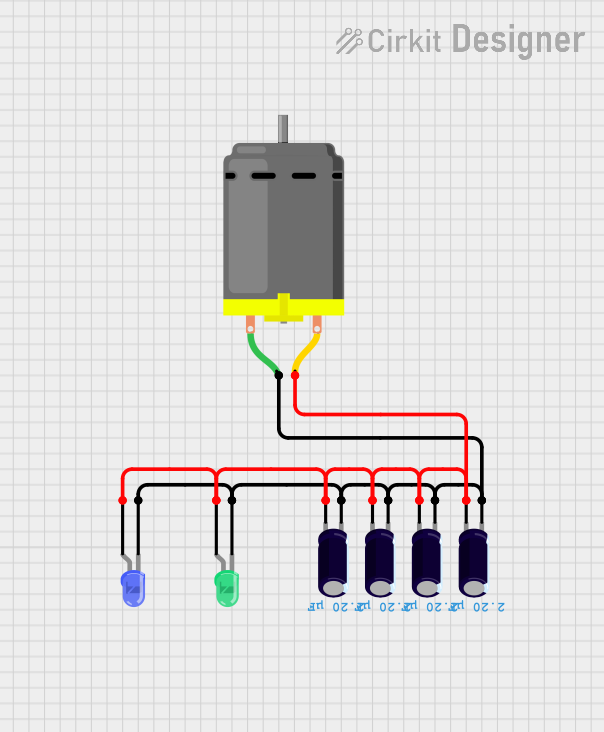
DC Motor with Capacitor Filtering and Dual LED Indicator

Circuit Documentation
Summary of the Circuit
The circuit in question appears to be a simple DC motor control circuit with decoupling capacitors and indicator LEDs. The DC motor is connected across two nets, with one net connecting to the negative terminals of the motor and the capacitors, as well as the cathodes of the LEDs. The other net connects to the positive terminals of the motor and the capacitors, along with the anodes of the LEDs. This configuration suggests that the capacitors are used to smooth out voltage spikes and noise, which is common in motor control applications to protect the circuit and reduce electromagnetic interference. The LEDs likely serve as power indicators or status indicators for the motor operation.
Component List
DC Motor
- Description: A standard direct current (DC) motor.
- Pins: pin 1, pin 2
- Purpose: To convert electrical energy into mechanical energy.
Electrolytic Capacitor
- Description: A polarized capacitor with a relatively high capacitance value.
- Pins: -, +
- Purpose: To provide decoupling and noise reduction in the circuit.
- Properties: Capacitance: 2.2 µF (microfarads)
LED: Two Pin (green)
- Description: A green light-emitting diode (LED).
- Pins: cathode, anode
- Purpose: To serve as a visual indicator, possibly to indicate power or status.
LED: Two Pin (blue)
- Description: A blue light-emitting diode (LED).
- Pins: cathode, anode
- Purpose: To serve as a visual indicator, possibly to indicate power or status.
Wiring Details
DC Motor
- Pin 1: Connected to the negative terminals (-) of all electrolytic capacitors and the cathodes of both LEDs.
- Pin 2: Connected to the positive terminals (+) of all electrolytic capacitors and the anodes of both LEDs.
Electrolytic Capacitors
- Negative Terminal (-): Connected to pin 1 of the DC Motor and the cathodes of both LEDs.
- Positive Terminal (+): Connected to pin 2 of the DC Motor and the anodes of both LEDs.
LED: Two Pin (green)
- Cathode: Connected to pin 1 of the DC Motor and the negative terminals (-) of all electrolytic capacitors.
- Anode: Connected to pin 2 of the DC Motor and the positive terminals (+) of all electrolytic capacitors.
LED: Two Pin (blue)
- Cathode: Connected to pin 1 of the DC Motor and the negative terminals (-) of all electrolytic capacitors.
- Anode: Connected to pin 2 of the DC Motor and the positive terminals (+) of all electrolytic capacitors.
Documented Code
There is no embedded code provided for any microcontrollers in this circuit. Therefore, this section is not applicable to the current documentation. If code is added at a later stage, it should be documented here with details on the microcontroller's role in the circuit, the functionality of the code, and any relevant algorithms or control strategies used.