
Arduino UNO-Based Water Quality Monitoring System with LCD Display
View and Edit Project In Cirkit Designer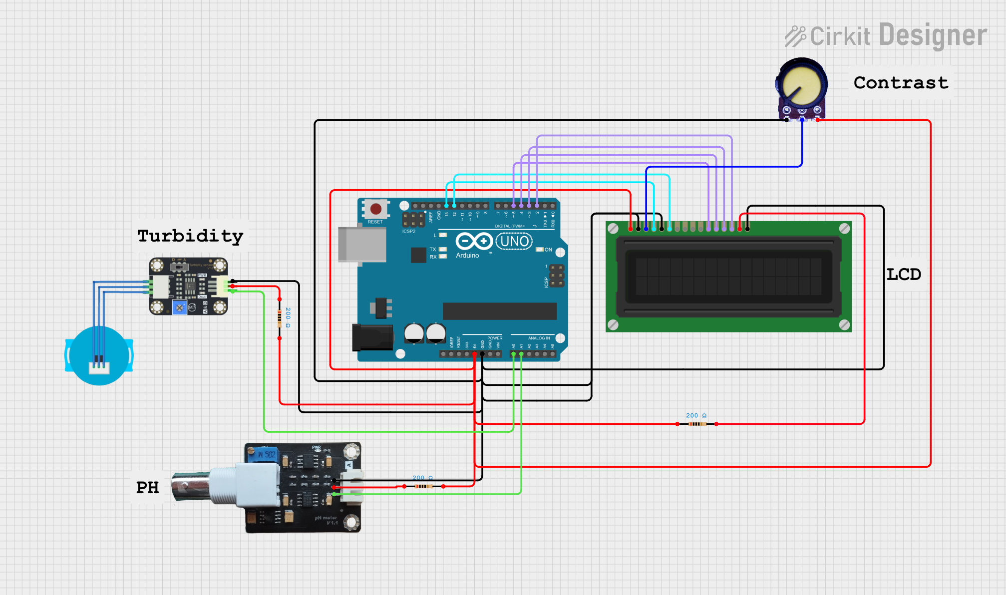
Circuit Documentation
Summary
This circuit involves an Arduino UNO microcontroller interfacing with various sensors and an LCD display. The sensors include a turbidity sensor and a pH meter. The circuit also includes resistors and a potentiometer for voltage regulation and signal conditioning. The LCD display is used to show the readings from the sensors.
Component List
Arduino UNO
- Description: A microcontroller board based on the ATmega328P.
- Pins: UNUSED, IOREF, Reset, 3.3V, 5V, GND, Vin, A0, A1, A2, A3, A4, A5, SCL, SDA, AREF, D13, D12, D11, D10, D9, D8, D7, D6, D5, D4, D3, D2, D1, D0
Resistor (200 Ohms)
- Description: A resistor with a resistance of 200 Ohms.
- Pins: pin1, pin2
Potentiometer
- Description: A variable resistor used to adjust voltage levels.
- Pins: GND, Output, VCC
LCD Display (16 pin)
- Description: A 16-pin LCD display used to show sensor readings.
- Pins: VSS, VDD, VO, RS, R_W, E, DB0, DB1, DB2, DB3, DB4, DB5, DB6, DB7, A, K
Turbidity Sensor
- Description: A sensor used to measure the turbidity of water.
- Pins: OUT, VCC, GND
pH Meter V1.1
- Description: A sensor used to measure the pH level of a solution.
- Pins: DATA, VCC, GND
Wiring Details
Arduino UNO
- 5V: Connected to pin2 of a resistor, pin1 of another resistor, VCC of the potentiometer, and VSS of the LCD display.
- GND: Connected to GND of the pH meter, GND of the turbidity sensor, GND of the potentiometer, VDD, K, and R_W of the LCD display.
- A0: Connected to OUT of the turbidity sensor.
- A1: Connected to DATA of the pH meter.
- D13: Connected to RS of the LCD display.
- D12: Connected to E of the LCD display.
- D5: Connected to DB4 of the LCD display.
- D4: Connected to DB5 of the LCD display.
- D3: Connected to DB6 of the LCD display.
- D2: Connected to DB7 of the LCD display.
Resistor (200 Ohms)
- pin1: Connected to pin2 of another resistor, VCC of the potentiometer, and VSS of the LCD display.
- pin2: Connected to pin1 of another resistor, VCC of the pH meter, and A of the LCD display.
Potentiometer
- GND: Connected to GND of the Arduino UNO.
- Output: Connected to VO of the LCD display.
- VCC: Connected to pin1 of a resistor, pin2 of another resistor, and VSS of the LCD display.
LCD Display (16 pin)
- VSS: Connected to pin1 of a resistor, pin2 of another resistor, and VCC of the potentiometer.
- VDD: Connected to GND of the Arduino UNO.
- VO: Connected to Output of the potentiometer.
- RS: Connected to D13 of the Arduino UNO.
- R_W: Connected to GND of the Arduino UNO.
- E: Connected to D12 of the Arduino UNO.
- DB4: Connected to D5 of the Arduino UNO.
- DB5: Connected to D4 of the Arduino UNO.
- DB6: Connected to D3 of the Arduino UNO.
- DB7: Connected to D2 of the Arduino UNO.
- A: Connected to pin2 of a resistor.
- K: Connected to GND of the Arduino UNO.
Turbidity Sensor
- OUT: Connected to A0 of the Arduino UNO.
- VCC: Connected to pin1 of a resistor.
- GND: Connected to GND of the Arduino UNO.
pH Meter V1.1
- DATA: Connected to A1 of the Arduino UNO.
- VCC: Connected to pin1 of a resistor.
- GND: Connected to GND of the Arduino UNO.
Documented Code
Arduino UNO Code (sketch.ino)
void setup() {
  // put your setup code here, to run once:

}

void loop() {
  // put your main code here, to run repeatedly:

}
Documentation (documentation.txt)
This documentation provides a comprehensive overview of the circuit, including a summary, detailed component list, wiring details, and the code used in the Arduino UNO microcontroller.